

Prototype assembly tolerance becomes important when several individually manufactured parts must create one controlled physical result. In our plastic prototyping projects, engineers may care more about the final housing gap, display alignment, cover flushness, or mating clearance than about any single dimension. I therefore start from the assembled condition and work backward to the locating features and dimensions that actually control it.
Prototype Assembly Tolerance Should Start With the Final Assembly Condition
Before assigning tighter tolerances to individual parts, I first ask what the assembled prototype actually needs to achieve. A multi-part product may need controlled clearance, visual alignment, repeatable location, smooth movement, or a consistent panel gap. That final condition should guide which dimensions deserve tighter manufacturing control.
A front housing, internal bracket, display holder, and rear cover may each have acceptable drawing dimensions. Yet the engineering team may ultimately judge the prototype by whether the display sits correctly inside the front opening. That result belongs to the assembly, not to one component alone.
This distinction changes how I review a multi-part prototype. Instead of treating every tolerance as an independent manufacturing target, I first identify the physical relationships that determine the final assembly condition. These may include how two housings locate against each other, how a display sits within an opening, or how adjacent panels maintain a consistent gap and alignment after assembly.
Once the required assembly condition is clear, I can work backward to the features that actually control it. This helps separate critical locating and mating relationships from dimensions that have little influence on the final result. The tolerance strategy can then focus manufacturing and inspection effort where dimensional variation directly affects fit, gap, alignment, clearance, or flushness.
A Part Dimension and an Assembly Result Are Not the Same Requirement
Suppose a display is positioned by a bracket, while that bracket is located by bosses inside a CNC-machined housing. The final display position depends on several relationships: the front opening, housing bosses, bracket mounting features, and display location on the bracket.
Tightening the display opening alone does not necessarily improve the final alignment. Likewise, making the bracket more accurate will not solve the problem if the housing locating relationship dominates the result.
This is why I separate part-level tolerance from assembly-level tolerance. Individual dimensions describe manufactured components; assembly requirements describe what those components must create together.
For engineers who need to define critical dimensions on individual components, we cover that subject separately in our guide to plastic manufacturing tolerances. This article moves one level higher and focuses on the relationships created after several parts come together.
Define Fit, Gap, Alignment, and Flushness as Different Requirements
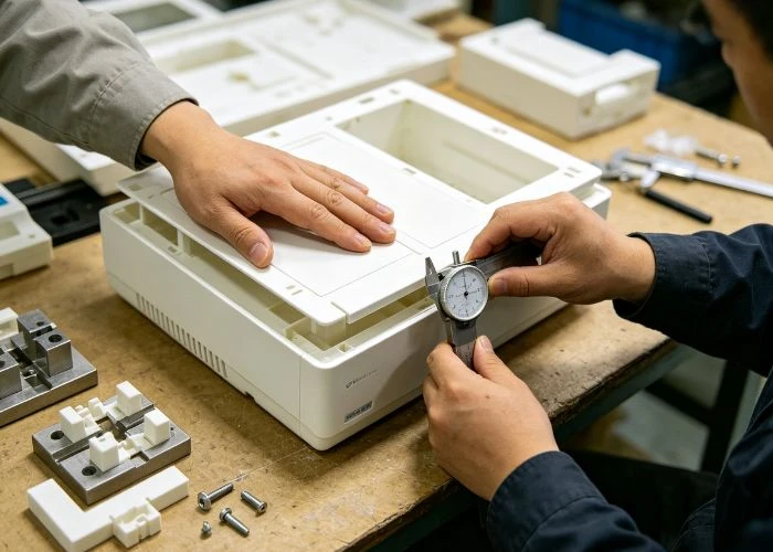
The word “fit” is often used too broadly in prototype projects. Two parts may assemble without interference but still have poor alignment, an uneven visible gap, or unacceptable surface height. I therefore separate these requirements before deciding how the prototype assembly tolerance should be specified and inspected.
| Assembly Requirement | What We Are Controlling | Typical Prototype Example |
| Fit | How two features physically mate | Locating pin and hole |
| Clearance | Available space between parts | Button and housing opening |
| Gap | Separation between adjacent parts | Front and rear housing |
| Alignment | Relative position between features | Display and housing opening |
| Flushness | Relative height of adjacent surfaces | Decorative panel and housing |
For a functional prototype, mechanical clearance may be the main concern. For an appearance prototype, a part can assemble correctly and still fail the evaluation because its visible gap or surface transition is inconsistent.
This is particularly important when CNC plastic machining and cosmetic finishing are combined. The manufacturing requirement must reflect what the engineering team will actually evaluate in the completed prototype.
Mechanical Fit Needs a Measurable Functional Limit
A requirement such as “good fit” is difficult to manufacture against because it does not explain what the prototype must demonstrate. A removable cover may need enough clearance for repeated removal, while a locating component may need much less movement once installed.
I prefer to connect the requirement to the intended physical behavior. Does the part need to slide freely? Should it locate repeatedly in the same position? Is slight movement acceptable? Must it install without force? These questions provide much more useful manufacturing information than simply asking for a “tight fit.”
Where possible, engineers should translate the expected behavior into measurable clearance, movement, location, or mating requirements. We can then identify which manufactured features actually control that result.
Cosmetic Gap and Flushness Need Their Own Acceptance Criteria
Consider two painted plastic housing panels. Mechanically, they may assemble without interference and all fasteners may engage correctly. But if the gap is visibly wider on one side, or one panel sits higher than the neighboring surface, the appearance prototype can still fail its purpose.
In this situation, mechanical fit and cosmetic acceptance are different requirements. The drawing or assembly information should therefore identify which visible transitions matter and what condition is acceptable after finishing and assembly.
This is especially useful for housings, display bezels, decorative covers, control panels, and other visible plastic prototyping components where the assembled appearance is part of the engineering review.
Prototype Assembly Tolerance Depends on Which Features Actually Locate the Parts
CAD defines every component in a nominal position, but the physical prototype reaches its actual assembly position through contact between specific locating features. Mounting surfaces, bosses, pins, shoulders, holes, and mating edges can all contribute to this relationship. For prototype assembly tolerance, the important point is to determine which of these features actually establishes the position of each component rather than assuming that every dimension shown in CAD contributes equally to the final assembly.
In a plastic housing assembly, for example, two locating bosses and a mounting surface may establish the primary position of one component, while screws only secure it after that position has already been defined. In another assembly, a pin-and-hole relationship may control lateral position while a shoulder determines the final seating depth. These locating relationships directly influence where the assembled components sit relative to each other.
Once the true locating features are identified, the tolerance strategy becomes much clearer. I can trace the dimensions that connect those features to the required fit, gap, alignment, or flushness and give them the appropriate level of control. Dimensions that do not significantly influence the final assembly condition can then be treated separately instead of being tightened unnecessarily. This creates a more practical connection between design intent, manufacturing control, and final assembly verification.
Locating Features and Fastening Features Do Different Jobs
A fastener primarily holds components together. A locating feature primarily determines their relative position. Although one feature can sometimes contribute to both functions, treating every screw hole as a precision locating feature can make assembly position less predictable.
For example, a screw passing through an oversized clearance hole can allow the panel to move before tightening. If there is no separate locating feature, the final position may depend on where the panel happens to sit while the screws are tightened.
That variation can change a visible gap or alignment even though the screw holes themselves meet their drawing requirements.
For critical assemblies, I therefore look for the geometry that establishes location first and the features that provide clamping second. Keeping these functions clear makes the final assembly condition easier to control.
Build the Shortest Tolerance Chain to the Final Assembly Result
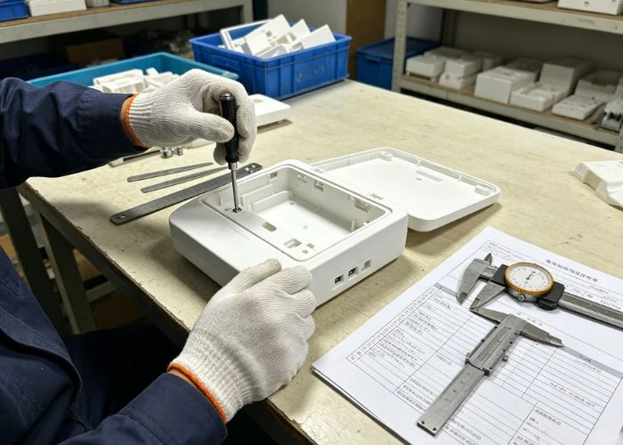
Tolerance stack-up matters in a multi-part prototype, but I do not begin by adding every dimension in the assembly. A useful tolerance chain contains only the dimensions and interfaces that can actually move the final result we are evaluating. Keeping that chain functional makes the analysis more useful for manufacturing.
Take the earlier display example. If the requirement is display alignment relative to the front opening, the relevant chain may include:
Front opening → housing locating boss → bracket locating feature → display mount → display edge
The overall housing length may appear on the same drawing, but if it does not move the display relative to the opening, it does not belong in that functional chain.
This prevents tolerance analysis from becoming a long calculation involving dimensions that do not change the engineering result.
Not Every Dimension Belongs in the Tolerance Chain
A useful tolerance chain should include only the dimensions that can influence the assembly result being controlled. Adding unrelated dimensions may make the analysis appear more complete, but it can also make it harder to identify which features actually require manufacturing and inspection attention. For this reason, I trace the dimensional relationship from the required assembly condition back through the locating and mating features that physically establish it.
For example, if a button must remain centered within a housing opening, its final position may depend on the location of the opening, the position of the button on the PCB or internal bracket, and the features that locate that PCB or bracket inside the housing. These dimensions form a meaningful chain because variation in any of them can shift the visible relationship between the button and the opening. A decorative feature elsewhere on the same housing does not affect that result and therefore should not be included simply because it belongs to the same part.
The same principle applies throughout a multi-part prototype. A dimension should contribute to a particular tolerance chain only when its permitted variation can change the fit, gap, alignment, clearance, or flushness being evaluated. Keeping the chain focused on these controlling relationships makes the prototype assembly tolerance easier to understand, manufacture, inspect, and verify without unnecessarily tightening dimensions that have little influence on the final assembly.
Do Not Tighten Every Part Tolerance to Fix an Assembly Requirement
When an assembly result has too much potential variation, tightening every contributing dimension may look like the safest response. In practice, that can increase CNC plastic machining and inspection effort without controlling the relationship efficiently. I first identify which features have the strongest influence on the final result.
Suppose a housing gap depends mainly on one locating boss and a mating edge. Reducing tolerances on unrelated internal pockets, overall dimensions, or cosmetic details does little to stabilize that gap.
A better approach is to concentrate manufacturing control on the geometry that establishes the assembly position. That may mean clarifying a locating relationship, controlling one feature more closely, changing how the result is referenced, or directly specifying the assembly requirement.
This approach is also consistent with practical DFM: manufacturing precision should be applied where it protects the prototype objective, rather than distributed equally across every feature. Our broader DFM for plastic prototyping guide explains how tolerance requirements interact with manufacturability before production.
Define Assembly Clearance From the Real Mating Components
Many plastic prototype assemblies contain parts that we do not manufacture, including displays, PCBs, switches, motors, connectors, lenses, fasteners, and other standard hardware. Their actual physical geometry can affect fit and clearance, so critical assembly requirements should not always rely on simplified nominal CAD alone.
A display model may define its overall envelope correctly while simplifying a connector, cable exit, seam, or local protrusion. A PCB model may not fully represent component height. A purchased fastener may also have a head or shoulder geometry that influences nearby clearance.
When these details affect the prototype assembly tolerance, the actual mating component provides more useful information than an assumption based only on nominal geometry.
For important interfaces, we therefore prefer to review confirmed component drawings or, where practical, incorporate customer-supplied components into the physical prototype build. UForProto’s existing complete prototype services workflow already supports the integration of displays, PCBs, switches, motors, fasteners, and other supplied components when they affect the physical assembly.
Surface Finishing Must Be Included in the Final Assembly Condition
For painted, polished, or cosmetically finished prototypes, I need to know whether an assembly requirement applies to the machined condition or the finished condition. CNC plastic machining may establish the base geometry, but later hand finishing or coating can still influence a critical interface or visible transition.
If a painted surface forms part of a controlled fit, masking or finishing strategy may be required to protect that interface. If two cosmetic panels form a visible joint, their final gap should be judged after the relevant finishing work has been completed.
Polishing requires a different consideration because material is removed rather than added. A transparent edge near a controlled interface may therefore need finishing attention without unnecessarily changing the relationship established during machining.
The solution is not to add finishing allowance to every assembly dimension. I identify the interfaces where finishing can change the final result and protect or verify those areas at the appropriate stage.
Define Prototype Assembly Tolerance Acceptance Before Trial Assembly
Prototype trial assembly is much more useful when the engineering team and manufacturer already know what constitutes an acceptable result. “It fits” is not enough for many projects. Before assembly, I prefer to understand which mechanical, dimensional, and cosmetic relationships actually need to be evaluated.
For example, acceptance may include:
Mechanical condition: components assemble without unintended interference and locating features seat correctly.
Dimensional condition: required clearance, installed position, or final gap remains within the specified range.
Alignment condition: displays, buttons, covers, or adjacent structures remain correctly positioned relative to their references.
Cosmetic condition: visible panel gaps and flushness remain acceptable after finishing.
These requirements do not need to become an unnecessarily complex inspection document. They simply need to tell us what the physical assembly is expected to demonstrate.
“It Fits” Is Not a Complete Acceptance Standard
A housing can close after screws are tightened and still have an uneven panel gap. A display can enter its opening but sit visibly off-center. A removable cover can be installed but require enough force to damage a painted edge.
All three examples technically “fit,” yet they represent different assembly problems.
I therefore avoid using successful installation as the only acceptance criterion. The relevant requirement should describe what matters after installation: clearance, position, alignment, movement, gap, flushness, or another measurable physical relationship.
Verify Prototype Assembly Tolerance at the Level Where the Requirement Exists
A prototype assembly tolerance should be verified at the same physical level where the requirement actually exists. Individual part inspection remains important, but it cannot confirm every relationship that matters after several components are assembled. A hole diameter, boss width, or machined opening can be measured directly on one component because the requirement belongs to that part. Clearance between a pin and a hole, however, depends on the relationship between two mating components, while display centering, housing gap, panel flushness, and multi-part alignment only become meaningful in the assembled condition.
This distinction affects how I plan inspection for a multi-part prototype. Part-level measurements help confirm that the manufactured geometry matches the drawing, while interface-level verification checks whether two mating features create the intended clearance, contact, or locating relationship. When the engineering requirement describes the final position or appearance of several components together, I verify that condition on the physical assembly rather than trying to infer it entirely from isolated measurements.
For example, a display bracket and a housing opening may both pass their individual dimensional inspections, but those results alone do not confirm that the display will appear correctly centered after assembly. The final position can also depend on the features that locate the bracket inside the housing and on the relationship between those features and the finished opening. If display centering is the actual engineering requirement, the completed assembly therefore needs to be evaluated against that requirement.
Using the correct verification level creates a clearer connection between the drawing, manufacturing inspection, and final prototype acceptance. Part dimensions are verified as part dimensions, mating relationships are checked at the interface, and requirements that only exist after assembly are confirmed on the assembled prototype. This prevents individual inspection results from being used as a substitute for verifying the fit, gap, alignment, clearance, or flushness that the prototype was actually built to demonstrate.
Dimensional Inspection and Prototype Fit Check Answer Different Questions
Dimensional inspection asks whether a specified feature meets its drawing requirement. A prototype fit check asks whether the real mating components create the intended physical relationship after they are brought together.
Both are useful, but one does not automatically replace the other. If a fit check reveals interference, misalignment, or an uneven gap, I first trace the problem back to the relevant locating and dimensional relationship rather than immediately modifying whichever part is easiest to reach.
We discuss that broader feedback loop in our complete prototype services article, where trial assembly is used to trace fit and alignment problems before the prototype is finalized.
How We Turn Assembly Requirements Into a Prototype Manufacturing Plan
At UForProto, as a direct plastic prototype manufacturer, we review assembly requirements before manufacturing begins to identify which relationships need the most control. Our role is not simply to manufacture each CAD component independently. We connect critical fit, gap, alignment, and clearance requirements with CNC plastic machining, surface finishing, inspection, and physical assembly verification. Our role is not simply to make each CAD component independently; we connect the relevant assembly requirements with machining, finishing, inspection, and physical verification.
For a multi-part project, I normally begin with the CAD assembly and identify the final relationships that matter:
Assembly requirement → locating features → relevant dimensional chain → manufacturing control → finishing condition → verification level
If a critical relationship is established during CNC plastic machining, we protect the relevant geometry there. If surface finishing can change the relationship, we account for the finished condition. If the requirement only exists when several parts come together, it is verified during prototype assembly.
This keeps manufacturing focused on the engineering result without turning every component into an unnecessarily tight-tolerance part.
Our existing prototype build services cover the broader manufacturing route from CAD review and part manufacturing through finishing, trial assembly, assembly verification, and delivery.
What Engineers Should Send for a Multi-Part Prototype Assembly
For a multi-part plastic prototyping project, the most useful starting point is the complete 3D CAD assembly together with individual part files. Critical 2D drawings should identify the dimensions and relationships that need specific control.
I also recommend providing the required fit, gap, alignment, or clearance information, plus material and surface-finishing requirements. If standard or customer-supplied components affect the assembly, their confirmed models, drawings, or physical samples are valuable.
Assembly information does not need to document every obvious step. It should focus on the relationships that change how we manufacture, finish, inspect, or assemble the prototype.
Conclusion
Effective prototype assembly tolerance starts with the final fit, gap, alignment, clearance, and flushness the assembled prototype must achieve—not by simply tightening every individual part tolerance. By identifying the true locating features and controlling the dimensional relationships that influence the final result, engineers can make multi-part prototypes easier to manufacture and verify. At UForProto, we combine plastic prototyping, CNC plastic machining, surface finishing, inspection, and prototype assembly to support these requirements. Send UForProto your CAD assembly, critical drawings, mating-component information, and assembly requirements for a project review and quotation.
FAQs
1. What Is Prototype Assembly Tolerance?
Prototype assembly tolerance describes the allowable variation in relationships created when multiple parts are assembled. Depending on the product, this can include final fit, clearance, gap, alignment, installed position, or flushness rather than only the dimensional tolerance of one component.
2. Can Every Prototype Part Be Within Tolerance and the Assembly Still Be Wrong?
Yes. Several acceptable dimensional variations can combine in the same assembly relationship. The final result also depends on which features physically locate the components. This is why part-level inspection and assembly-level verification answer different engineering questions.
3. How Should Engineers Specify a Gap Between Two Prototype Parts?
Define the required gap together with its allowable variation and the assembly condition under which it applies. For cosmetic joints, it may also be important to control gap consistency across the visible edge rather than specifying only one nominal measurement.
4. Should Screw Holes Be Used to Control Prototype Part Alignment?
Not automatically. Screw holes often provide clearance for fastening rather than precise location. Where alignment is critical, dedicated locating bosses, pins, mating surfaces, shoulders, or other controlled features can provide a clearer physical reference for the assembled position.
5. Should Prototype Assembly Tolerance Be Checked Before or After Painting?
It depends on where the requirement becomes final. Machined interfaces may be checked before finishing, while visible gaps, flushness, or coating-sensitive fits should also be evaluated in the finished condition. Critical mating areas may need masking or protection during painting.
6. What Files Should I Send for a Multi-Part Prototype Assembly?
Send the complete 3D CAD assembly, individual part files, critical 2D drawings, and the required fit, gap, alignment, or clearance information. Material, surface finish, fastening information, and confirmed data for customer-supplied components should also be included when they affect the assembly.