
CNC Acrylic Design requires more than creating an accurate CAD model. For transparent PMMA housings, engineers must consider how internal structures, mounting features, wall geometry, and polishing affect both appearance and assembly. A housing may meet its dimensional requirements yet still reveal unwanted tool marks, visible fasteners, or inconsistent edge clarity. During plastic prototyping, these issues are easier to address before the design is finalized. In this guide, we share seven practical design considerations for developing clear acrylic housings that balance manufacturability, visual quality, dimensional accuracy, and prototype assembly requirements.
1. What Makes CNC Acrylic Housing Design Different?
CNC Acrylic Design differs from ordinary opaque housing design because transparency exposes features that would otherwise remain hidden. Internal pockets, fastening hardware, machining marks, and wall transitions can influence the appearance of a clear component. We recommend evaluating the housing as a complete visual and mechanical system rather than treating transparency as a finishing requirement added after machining.
In an opaque ABS enclosure, a rear mounting boss may have little influence on the visible exterior. In a clear PMMA housing, the same boss may be visible through the front wall, changing the perceived shape of the product.
The same principle applies to internal tool marks. A machined cavity that would be acceptable inside an opaque housing may become visually distracting when viewed through a transparent wall.
We therefore recommend identifying the intended viewing directions during the CAD review. Engineers should consider how the component will appear from the front, sides, and any other angles relevant to product evaluation.
Another consideration is the relationship between the exterior surface and the internal geometry. Thick transitions, deep recesses, and curved walls can alter how light travels through the part, producing visible distortion even when the material itself is clear.
This is why a visually successful acrylic prototype requires more than smooth external surfaces. The internal design, material thickness, and final assembly condition should support the intended appearance.
In CNC plastic machining, we also need to distinguish surfaces that must remain dimensionally accurate from surfaces intended for additional finishing. This distinction becomes increasingly important when the housing contains both cosmetic and functional features.
For a general explanation of machining PMMA and its common manufacturing problems, see our related CNC Acrylic Machining guide.
2. How Should Engineers Plan Clear Viewing Areas and Hidden Structural Features?
A clear acrylic housing often serves two purposes: it protects or supports internal components while allowing users to see selected features. These functions can conflict when mounting structures occupy the viewing area. We recommend dividing the housing into visual, structural, and assembly zones during the early design stage so that each area has a clearly defined purpose.
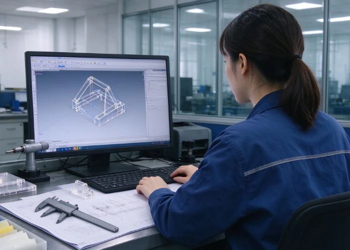
The viewing zone is the part of the housing where transparency matters most. It may cover a display, indicator, fluid chamber, internal mechanism, or decorative product feature.
We recommend defining this area in the CAD model or engineering drawing rather than relying on a general instruction such as “make the entire housing transparent.” A defined viewing zone helps determine which surfaces require additional finishing and inspection.
The structural zone contains features that support the product, such as mounting bosses, locating shoulders, brackets, and reinforced edges. Where practical, these features can be positioned outside the primary viewing area.
For example, an industrial inspection housing may use a clear front window and a thicker perimeter for fastening. This allows the central viewing area to remain relatively unobstructed while the surrounding structure carries installation loads.
The assembly zone includes the interfaces that connect the acrylic housing to adjacent components. We recommend checking whether fasteners, inserts, adhesives, or support brackets will remain visible through the completed enclosure.
A transparent housing can also reveal components behind it that were never intended to become part of the product’s visual design. Wires, unfinished brackets, and internal labels may influence the appearance of a cosmetic prototype.
We recommend evaluating the complete prototype assembly rather than judging the acrylic component alone. A housing that looks clear on the inspection table may produce a different visual result after installation.
This approach is especially useful for medical device housings, laboratory instruments, consumer electronics, and industrial equipment where both appearance and internal visibility influence design approval.
3. What Wall Thickness and Corner Designs Work Best for CNC Acrylic Housings?
Wall thickness, corner geometry, and pocket depth affect how an acrylic housing is manufactured and supported. These features also influence stiffness, tool access, and the visual appearance of transparent walls. We recommend selecting dimensions according to the housing’s actual geometry and intended function rather than applying one universal wall thickness or corner radius to every PMMA prototype.
How Can Wall Thickness Affect Transparent Housing Quality?
A thin acrylic wall may provide the desired appearance but become difficult to support during machining. Long unsupported sections can deflect under cutting forces, making it harder to maintain consistent geometry.
Wall thickness also affects the visual relationship between internal and external surfaces. A large change in thickness may be noticeable through clear PMMA, particularly around transitions between a main wall and a mounting feature.
We recommend keeping critical viewing areas as geometrically consistent as practical. This does not mean every wall must have identical thickness; structural requirements may justify local reinforcement.
For example, a transparent device cover may require a relatively thin viewing panel and a thicker fastening flange. Separating these functions allows the design to support assembly without unnecessarily increasing the thickness of the visible area.
We also recommend checking the remaining wall thickness after pocket machining. A nominal wall that appears adequate in CAD may become vulnerable when adjacent cavities, holes, or finishing allowances are considered together.
How Should Internal Corners and Deep Pockets Be Designed?
CNC milling tools have a finite diameter, so internal vertical corners cannot be produced as perfectly sharp corners using ordinary end milling. Appropriate corner radii should be included where the functional design permits.
A radius can improve tool accessibility and reduce the need for very small cutters. However, it must remain compatible with mating components and the intended assembly clearance.
Deep pockets introduce another consideration: the relationship between cutter reach and the surrounding walls. A narrow, deep cavity may require long tools or multiple machining strategies, increasing the difficulty of achieving a consistent finish.
For transparent housings, we recommend evaluating whether the internal pocket will be visible after assembly. If it will, the design should allow enough access for the required finishing method.
An inaccessible internal surface may be manufacturable but difficult to polish. This is a design limitation rather than simply a machining quality issue.
We recommend reviewing these relationships during the DFM stage. Our design for manufacturability guide provides additional context for evaluating feature accessibility and manufacturing constraints.
4. How Should Mounting Holes and Fastening Features Be Designed in PMMA Housings?
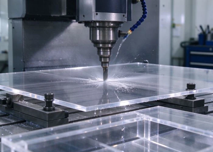
Mounting features are essential to prototype assembly, but they can introduce concentrated loads into acrylic components. The design must account for hole location, fastener clearance, tightening force, and repeated assembly. We recommend treating fastening as a load-transfer problem rather than simply placing holes wherever they fit within the available CAD geometry.
Should Acrylic Housings Use Threaded Holes or Clearance Holes?
Directly tapped PMMA holes can be appropriate for selected low-load prototype applications. However, the suitability depends on thread engagement, component thickness, assembly frequency, and expected fastening load.
When a connection will be repeatedly assembled and disassembled, we recommend evaluating metal inserts or other reinforced fastening solutions. These can reduce repeated loading on the plastic threads when correctly selected and installed.
A clearance-hole connection with a suitable washer may be preferable when the goal is to clamp two components together without relying on the acrylic itself to provide the threaded engagement.
We also recommend avoiding unnecessary interference between a screw shank and the hole wall. A hole that is too restrictive may introduce additional stress when the components are assembled.
The ACRYLITE machining guide notes that acrylic can be threaded and discusses the use of metal inserts where threaded connections are repeatedly loosened. The final connection still needs to be assessed against the project’s loads and geometry.
How Can Engineers Prevent Fasteners From Affecting Clear Surfaces?
A screw head, washer, or insert can become a prominent visual feature when viewed through clear PMMA. We recommend considering the position and appearance of these components during the housing design stage.
Where practical, fasteners can be positioned along a perimeter flange or outside the primary viewing area. This allows the housing to retain its mounting function while reducing visual obstruction.
Countersunk screws require particular care. The conical contact surface can create concentrated loading if the geometry, alignment, or tightening condition is unsuitable.
We recommend reviewing the contact geometry and considering load-distributing alternatives where appropriate. The preferred solution should be based on the actual prototype requirements rather than appearance alone.
Hole edges should also be properly finished. Deburring and appropriate edge treatment can reduce local notch effects and help prevent damage during handling or assembly.
For reference, PLEXIGLAS drilling guidance emphasizes appropriate drilling tools, workpiece support, and hole-edge finishing.
5. How Can CNC Acrylic Polishing Be Planned During the Design Stage?
CNC acrylic polishing should be considered before manufacturing begins because finishing access and material removal can influence the final geometry. A surface that is easy to machine may still be difficult to polish, especially inside a deep cavity or near a narrow opening. We recommend defining finishing priorities in the design documentation rather than applying one polishing requirement to the entire housing.
Which Acrylic Surfaces Need Polishing?
Not every machined PMMA surface requires the same finish. A clear viewing face may need a high level of visual clarity, while a hidden mounting surface may only require a suitable machined finish and dimensional accuracy.
We recommend identifying visible surfaces directly on the drawing. A simple surface classification can help the manufacturer determine where finishing effort is necessary.
For example, a transparent instrument housing may require polished front and side faces but allow an ordinary machined finish on an internal mounting platform.
This approach can reduce unnecessary finishing time and avoid modifying surfaces that are critical to assembly.
How Does Polishing Affect Dimensions and Edge Geometry?
Mechanical polishing removes a small amount of material while reducing surface irregularities. The amount removed depends on the starting surface, finishing method, operator control, and geometry.
On a large decorative surface, limited material removal may have little functional effect. Around a precision opening or mating edge, however, the same process can influence clearance or alignment.
We recommend protecting critical interfaces from unnecessary polishing and specifying any required finishing allowance during the design review.
Edge rounding is another concern. Polishing can soften the appearance of a machined edge, but excessive rounding may change the intended joint line or fit.
We therefore recommend inspecting critical dimensions after the final finishing operation, not only immediately after CNC machining.
The PLEXIGLAS sanding and polishing guide also highlights the importance of controlling frictional heat during finishing. Excessive pressure or prolonged polishing can introduce surface damage.
Comparison Table — Surface Finishing Priorities for Clear PMMA Housings
| Surface Type | Main Requirement | Design Consideration |
| Clear viewing face | High visual clarity | Provide accessible finishing area |
| Decorative exterior | Consistent appearance | Avoid visible transitions and scratches |
| Internal visible cavity | Defined cosmetic quality | Check tool and polishing access |
| Mounting surface | Dimensional accuracy | Minimize unnecessary material removal |
| Precision opening | Fit and edge quality | Control edge rounding |
We recommend using this classification as a starting point rather than a universal finishing standard. Each project should define its own acceptable surface condition and inspection criteria.
6. How Can Engineers Balance Transparency and Dimensional Accuracy?
Transparent acrylic housings often combine cosmetic requirements with precision assembly features. These requirements may conflict when polishing, edge finishing, or structural modifications change critical dimensions. We recommend separating visual acceptance criteria from dimensional acceptance criteria and identifying where the two overlap. This allows the prototype to be evaluated against its intended function rather than one generalized quality description.
Consider a transparent display housing with a polished outer face and a precisely located internal mounting shoulder. The outer face must meet the cosmetic target, while the shoulder controls the position of an adjacent component.
If both surfaces receive the same finishing treatment without considering their functions, the final assembly may no longer match the original design.
We recommend assigning critical dimensions to the functional interfaces and specifying cosmetic requirements separately for the visible surfaces. The drawing should make it clear which features require final inspection after finishing.
For cosmetic acceptance, the team should agree on viewing distance, lighting, orientation, and the types of visible defects that are acceptable. Without these conditions, two inspectors may reach different conclusions about the same part.
Dimensional acceptance should be based on specified datums, measurement locations, and drawing tolerances. We recommend checking the component in the appropriate condition, including after finishing and, where relevant, after assembly.
A third category may be needed when optical performance matters. Visual transparency does not automatically establish optical-grade quality, and requirements such as haze, distortion, or light transmission need their own specifications and suitable test methods.
We recommend clarifying these requirements before the quotation stage. This helps distinguish a cosmetic display prototype from a component that requires formal optical characterization.
In plastic prototyping, the most useful outcome is a sample that answers the intended engineering question. A transparent prototype can be successful for appearance review even when it is not designed to meet the complete performance requirements of the final product.
7. What Should Engineers Check Before Approving a Transparent PMMA Housing Prototype?
A transparent PMMA housing should be evaluated as both an individual component and part of its intended assembly. We recommend preparing a design review checklist before manufacturing so that cosmetic, dimensional, and installation requirements are not overlooked. The objective is to identify whether the prototype supports the next engineering decision, not merely whether the part looks attractive.
The first review should confirm the intended viewing areas. We recommend checking whether internal structures, fasteners, or unexpected reflections interfere with the product’s visual concept.
Next, the team should inspect the critical geometry. This includes mounting interfaces, remaining wall thickness, pocket depth, and features that must align with neighboring components.
Surface quality should be reviewed after the required finishing is complete. We recommend examining the visible areas under agreed lighting conditions and recording any scratches, haze, inconsistent edges, or other relevant observations.
The final review should include trial assembly where applicable. A housing may pass individual inspection yet reveal a problem when installed against a bracket, bezel, or another plastic component.
Design Review Checklist for CNC Acrylic Housings
| Review Item | Engineering Question |
| Viewing area | Are important visual features unobstructed? |
| Internal geometry | Are visible internal features acceptable? |
| Wall thickness | Is the geometry suitable for machining and support? |
| Mounting holes | Are fastener loads and clearances appropriate? |
| Polishing access | Can the required surfaces be finished? |
| Critical dimensions | Are functional interfaces protected and inspected? |
| Cosmetic quality | Does the finished part meet the agreed visual criteria? |
| Prototype assembly | Does the housing fit its mating components? |
We recommend documenting the CAD revision, inspection results, and any required corrections. If a prototype needs modification, the next revision should address the specific observed issue rather than introducing unrelated design changes.
This is particularly important for appearance prototypes that will be reviewed by both engineering and industrial design teams. Clear acceptance criteria help ensure that each team evaluates the same intended outcome.
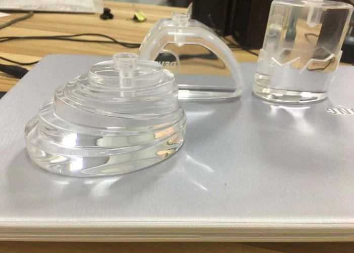
How Can a Plastic Prototype Manufacturer Support Clear Acrylic Housing Development?
A direct plastic prototype manufacturer can help engineers translate transparent housing requirements into practical manufacturing decisions. We recommend sharing the CAD model, critical dimensions, intended viewing areas, and surface finish expectations early in the project. This allows the manufacturing team to evaluate whether the design supports the required geometry, finishing access, and physical assembly.
At UForProto, we manufacture plastic prototypes directly in our factory in Foshan, China. Our services include CNC plastic machining, SLA/SLS 3D printing, vacuum casting, surface finishing, and prototype assembly.
For clear PMMA housings, we can review machining feasibility, critical interfaces, and the intended cosmetic requirements before production begins. This helps identify areas where geometry or finishing expectations may need clarification.
We recommend distinguishing the surfaces that require visual clarity from those that require dimensional control. This allows the manufacturing plan to focus on the actual development priorities.
For projects involving several components, our complete prototype services can support coordinated part manufacturing, suitable finishing, and physical prototype assembly.
We do not provide injection molding production or complete-machine functional testing. For prototypes with specialized optical performance requirements, the inspection and validation scope should be agreed upon separately.
If you are developing a transparent acrylic housing prototype, send your CAD files, drawings, and design requirements to info@uforproto.com for a manufacturing review and quotation.
Conclusion
Successful CNC Acrylic Design requires engineers to consider transparency, structural geometry, fastening, polishing, and dimensional accuracy as connected requirements. Clear PMMA housings reveal internal details that opaque components can hide, making early visual planning essential. Wall thickness, corner geometry, and mounting features should support both manufacturing and assembly. Polishing requirements must also be defined before machining to protect critical interfaces and avoid unnecessary finishing. We recommend using clear design documentation, appropriate inspection criteria, and physical prototype evaluation to confirm the intended result. By addressing these factors during plastic prototyping, engineering teams can make more informed design revisions and improve the reliability of transparent housing development.
FAQs
1. What Is the Best Wall Thickness for a CNC Acrylic Housing?
There is no universal wall thickness for every acrylic housing. We recommend selecting thickness based on part size, unsupported length, machining access, fastening loads, and the intended prototype function.
2. Can Acrylic Housings Have Threaded Holes?
Yes. PMMA can be tapped for selected applications, but repeated assembly or higher fastening loads may justify metal inserts or alternative connection designs.
3. How Should Mounting Holes Be Designed in PMMA Parts?
We recommend evaluating edge distance, hole clearance, fastener contact pressure, and the surrounding wall geometry. Proper support and edge finishing also help reduce assembly-related damage.
4. Does Polishing Change CNC Acrylic Part Dimensions?
Yes. Mechanical polishing removes material and can alter edge geometry. We recommend identifying critical interfaces before finishing and inspecting relevant dimensions afterward.
5. Can Internal Surfaces of Acrylic Housings Be Polished?
Some internal surfaces can be polished, but accessibility depends on cavity depth, opening size, and geometry. We recommend reviewing finishing access during the CAD design stage.
6. How Do Engineers Evaluate a Transparent Acrylic Prototype?
We recommend reviewing viewing-area clarity, internal appearance, critical dimensions, mounting features, and assembly fit. Optical performance should be evaluated separately when formal specifications apply.