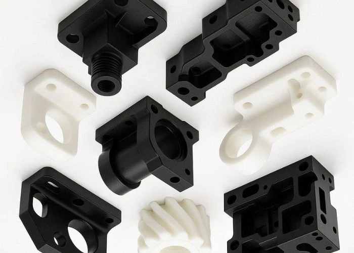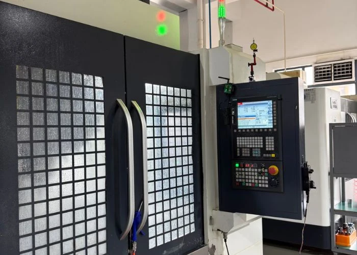

Automotive interior plastic components play an important role in vehicle appearance, functionality, and assembly. From dashboard housings and center console panels to decorative trim and control bezels, these parts must meet dimensional, structural, and cosmetic requirements. However, a component that looks correct in CAD may reveal unexpected gaps, mounting interference, or surface inconsistencies during physical assembly. In this guide, we explain how automotive interior housings and trim parts are designed, what engineers should consider during plastic prototyping, and how manufacturing and prototype assembly help identify design issues before production tooling.
1. What Are Automotive Interior Plastic Components?
Automotive interior plastic components are manufactured parts used throughout a vehicle cabin to provide structural support, protective coverage, user interfaces, and decorative surfaces. Their functions range from supporting electronic modules to creating consistent visible transitions between interior panels. We recommend distinguishing the intended function of each component before evaluating its material, geometry, or manufacturing requirements.
Automotive interior components are commonly divided into housings, structural supports, trim panels, bezels, covers, and smaller interface components. Although these categories overlap, their design priorities are often different.
A display housing, for example, may require accurate mounting interfaces and sufficient clearance for internal electronics. A decorative trim panel may place greater emphasis on surface appearance, consistent gaps, and secure attachment to neighboring components.
Some components combine both functions. A center console panel may provide a visible cosmetic surface while also supporting switches, buttons, or other user-interface elements.
For a broader understanding of materials, applications, and manufacturing methods beyond the vehicle cabin, explore our guide to Plastic Automotive Components.
2. What Types of Plastic Housings Are Used in Automotive Interiors?
Plastic housings are used to protect internal components, establish mounting positions, and organize assemblies within the vehicle cabin. Their design requirements depend on the equipment they contain and the surrounding interior structure. We recommend evaluating housing geometry according to mounting accuracy, available installation space, access requirements, and the relationship between visible and concealed surfaces.
Dashboard and Instrument Cluster Housings
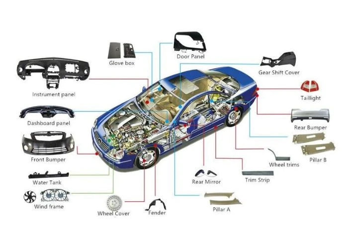
Dashboard and instrument cluster housings support displays, indicators, control modules, and related components. Their mounting interfaces must position these elements correctly relative to the surrounding dashboard structure.
In plastic prototyping, we pay particular attention to mounting holes, internal supports, connector openings, and clearance around neighboring parts.
A prototype housing can help engineers confirm whether the display sits at the intended position and whether the surrounding bezel covers the required edges without creating interference.
For a CNC-machined prototype, we can inspect critical mounting dimensions and evaluate the physical fit with customer-supplied components. This provides information that cannot be obtained from an isolated CAD model alone.
Center Console and Electronic Control Housings
Center console housings may support storage compartments, electronic interfaces, switches, and decorative covers. These assemblies often contain multiple plastic parts that must align within a limited installation space.
We recommend identifying the interfaces that determine the position of each component. A small deviation in a mounting bracket can influence the visible position of a neighboring panel.
Prototype assembly is especially useful when the design includes several covers, buttons, and support structures. We can examine their physical relationships before the design moves toward production preparation.
Air Vent, Control Panel, and Interior Equipment Housings
Air vent housings, control panel frames, and equipment covers are additional examples of automotive interior plastic components. Their geometry often combines functional openings with mounting features and visible exterior surfaces.
For an air vent prototype, the engineering focus may include the position of internal supports, the clearance around adjustable components, and the fit between the vent frame and surrounding trim.
The prototype can help identify mechanical interference and assembly problems. However, physical fit verification should not be confused with complete airflow, durability, or vehicle-level functional validation.
3. What Are the Main Types of Automotive Interior Plastic Trim Parts?
Automotive interior trim parts create the visible surfaces and transitions that define the cabin’s appearance. Unlike concealed housings, these components are frequently evaluated through color, texture, alignment, and the consistency of their edges. We recommend considering the trim panel’s appearance together with its attachment system, because mounting conditions can influence how the finished surface sits within the assembly.
Common examples include dashboard trim strips, door panel decorative covers, center console bezels, instrument panel frames, and control-interface surrounds.
A dashboard trim strip may extend across several adjacent components. Even if the strip itself is manufactured accurately, differences in the supporting surfaces can create visible changes in alignment.
Door panel trim presents a different challenge. The decorative surface must follow the intended contour while remaining securely attached to the supporting panel.
For control bezels, the relationship between the visible opening and the underlying switch or display is particularly important. An opening that is dimensionally correct may still appear misaligned if the supported component sits in an unexpected position.
We recommend distinguishing three requirements during trim prototype development: the appearance of the individual part, the accuracy of its mounting interfaces, and the visual result after assembly.
A prototype should be evaluated against all three when relevant. This helps prevent teams from approving a decorative surface that looks correct by itself but does not integrate properly with the surrounding interior.
4. Which Materials Are Suitable for Automotive Interior Plastic Prototypes?
Material selection for automotive interior plastic components depends on the prototype’s purpose, expected mechanical behavior, surface appearance, and manufacturing process. A material suitable for cosmetic evaluation may not reproduce the performance of the intended production resin. We recommend selecting prototype materials according to the engineering questions being investigated rather than assuming that one plastic can represent every interior application.
ABS is commonly considered for interior housings, bezels, and cosmetic prototypes because it offers a useful combination of machinability, rigidity, and surface-finishing potential.
PC may be considered when impact resistance or toughness is important. However, the specific grade, geometry, and prototype manufacturing method influence the actual behavior.
PMMA is useful for transparent display covers and selected decorative components where visual clarity is a major requirement. Its relatively brittle behavior must be considered around mounting features.
PP may be relevant when the production design requires flexibility or chemical resistance, while POM can be considered for certain precision mechanical interfaces. These materials should not be treated as interchangeable.
Comparison Table — Materials for Automotive Interior Plastic Prototyping
| Material | Typical Prototype Application | Main Consideration |
| ABS | Housings, bezels, cosmetic panels | Machinability and finishing |
| PC | Protective covers, selected structural parts | Toughness and dimensional requirements |
| PMMA | Clear covers, display windows | Clarity and stress sensitivity |
| PP | Selected covers and flexible features | Material flexibility and processing behavior |
| POM | Precision locating or moving components | Wear behavior and dimensional control |
This comparison is intended for prototype planning rather than final automotive material qualification. Production material approval may require separate evaluation of flammability, heat aging, impact performance, emissions, and other applicable specifications.
We also recommend identifying whether the prototype must match the intended production material or simply reproduce its geometry and appearance. This decision can significantly affect manufacturing cost and the interpretation of test results.
5. How Should Engineers Design Mounting Features for Automotive Interior Plastic Components?
Mounting features determine how interior housings and trim parts connect to supporting structures. Clips, screws, locating pins, bosses, and brackets each introduce different constraints. We recommend defining the intended assembly sequence and load path before finalizing these features. A connection should not only hold the part in place but also support repeatable positioning and practical installation.
How Should Clips and Snap-Fit Features Be Evaluated?
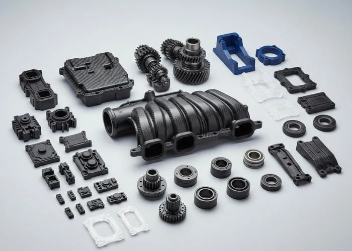
Plastic clips are widely used in interior trim assemblies because they can support installation without placing visible fasteners on the exterior surface.
However, a clip must be evaluated according to its intended retention force, installation movement, material behavior, and service requirements.
A clip that is too stiff may be difficult to install or may damage the surrounding structure. A connection with insufficient retention may allow unwanted movement between adjacent components.
Research published by SAE International on automotive trim clip design examines how clip design and material selection relate to retention, durability, and interior noise behavior.
For plastic prototyping, we recommend identifying whether a clip is being evaluated for geometric fit, assembly feasibility, or actual mechanical performance.
A CNC-machined or 3D-printed representation may help check available space and assembly geometry. It does not automatically reproduce the flexibility, fatigue resistance, or retention behavior of a production-molded clip.
How Can Locating Features Improve Assembly Accuracy?
Locating features establish the position of a component relative to its supporting structure. These may include pins, holes, slots, shoulders, and controlled contact surfaces.
We recommend distinguishing locating features from fastening features. A screw may provide clamping force, while a separate locating feature controls the intended position.
When too many features attempt to constrain the same movement, the assembly may become overconstrained. This can make installation difficult or introduce deformation when the fasteners are tightened.
For example, a design may use one primary locating hole and a secondary slot to control orientation while allowing a defined direction of adjustment. Whether this arrangement is appropriate depends on the actual engineering requirements.
During prototype assembly, we can observe whether locating features engage naturally or require excessive force. This helps identify geometric conflicts before the design is finalized.
6. How Do Gap, Flushness, and Tolerance Stack-Up Affect Interior Trim Assembly?
Automotive interior plastic components are often judged by how consistently they align with neighboring parts. A panel can meet its individual drawing tolerances and still produce an unacceptable visible joint after assembly. We recommend evaluating gap, flushness, and tolerance stack-up as relationships between components rather than isolated measurements on a single part.
Gap refers to the separation between adjacent edges or surfaces. Flushness describes the relative height or offset between neighboring visible surfaces.
For example, a center console bezel may have an even gap along one edge but sit higher than the neighboring panel. The gap and flushness therefore need to be evaluated separately.
We recommend defining measurement locations and reference conditions before manufacturing. Without a consistent setup, measurements taken at different points or under different fastening conditions may not be comparable.
Tolerance stack-up becomes important when several components contribute to the final position. The combined variation may be greater than the variation of any individual part.
Consider a simplified dimensional chain containing three independent dimensions, each specified at ±0.20 mm. If all three dimensions contribute in the same direction, the arithmetic worst-case variation is ±0.60 mm.
This is only an illustrative calculation, not a universal automotive tolerance requirement. Actual stack-up analysis must account for the correct dimensional chain, datum relationships, assembly constraints, and the selected analysis method.
Comparison Table — Interior Assembly Quality Factors
| Factor | What It Evaluates | Prototype Check |
| Gap | Separation between adjacent parts | Measure at defined joint locations |
| Flushness | Relative surface height | Compare surfaces under defined assembly conditions |
| Datum alignment | Position relative to references | Inspect locating interfaces |
| Tolerance stack-up | Combined dimensional variation | Review the complete dimensional chain |
| Assembly distortion | Shape change after fastening | Inspect before and after assembly |
When an assembled panel shows an uneven gap, we recommend checking the locating interfaces and supporting structure before changing the visible edge geometry.
Removing material from the wrong edge may temporarily improve one joint while creating a new problem elsewhere. The objective is to identify the actual cause of the misalignment.
7. How Should Surface Finish and Appearance Be Evaluated on Interior Plastic Prototypes?
Interior plastic components are often evaluated under direct visual inspection, making surface finish an important part of prototype approval. Color, gloss, texture, coating consistency, and visible defects can affect the perceived quality of the assembly. We recommend establishing cosmetic requirements separately from dimensional tolerances so that appearance expectations are clear before manufacturing begins.
A CNC-machined ABS prototype may be suitable for painting when the project requires a particular color or cosmetic appearance. However, the finished result depends on the preparation process, coating system, and specified acceptance criteria.
For trim components, visual consistency between adjacent parts may matter more than the appearance of an isolated sample. Two panels can look acceptable individually but show noticeable differences when installed next to each other.
We recommend reviewing color and gloss under agreed lighting conditions. Viewing direction and surrounding materials can influence the visual comparison.
The SAE J361 procedure for visual evaluation of automotive trim provides a relevant reference for evaluating color matches in applicable opaque or nearly opaque trim materials.
It is also important to distinguish prototype cosmetic finishing from production texture replication. A painted or manually finished prototype may communicate the intended appearance without reproducing every characteristic of a production-molded surface.
We recommend documenting which surfaces are cosmetic-critical, which are hidden after assembly, and which must maintain precise dimensions.
This distinction helps avoid unnecessary finishing on concealed interfaces and reduces the risk of changing critical dimensions during sanding, painting, or other finishing operations.
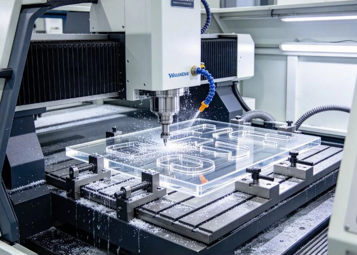
8. How Can CNC Plastic Machining Support Automotive Interior Prototype Design?
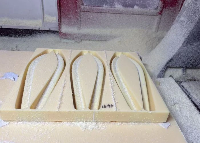
CNC plastic machining is useful when automotive interior prototypes require accurate mounting interfaces, defined geometry, and physical parts for assembly evaluation. We recommend selecting the manufacturing process according to the prototype’s purpose rather than assuming every interior component should be produced in the same way. CNC machining is particularly valuable when engineers need to inspect and modify specific structural features.
For example, a prototype display housing may contain mounting holes, pockets, support shoulders, and external cosmetic surfaces. CNC machining can produce these features directly from suitable plastic stock.
The resulting part can be measured and assembled with neighboring components. If a mounting position needs revision, the CAD model can be updated and a revised prototype manufactured without waiting for production tooling.
CNC machining is also suitable for selected trim components, especially when the project requires a rigid cosmetic model or an accurately positioned bezel.
However, large thin panels, complex undercuts, and flexible snap-fit features may create machining limitations. In these cases, we recommend evaluating whether another prototyping process is more appropriate for the specific feature.
SLA or SLS 3D printing can support rapid geometry evaluation when the design contains difficult-to-machine features. Vacuum casting may be considered when several similar prototype parts are needed.
The manufacturing route should also reflect the intended production design. A CNC-machined prototype does not automatically reproduce injection-molded material behavior, molded-in stress, surface texture, or clip performance.
For more general guidance on improving manufacturability, our DFM for Plastic Prototyping article explains how geometry, tolerances, machining access, and finishing requirements influence prototype production.
9. What Should Engineers Verify During Automotive Interior Prototype Assembly?
Prototype assembly allows engineers to evaluate relationships that may not be apparent when components are inspected separately. Interior housings, trim panels, bezels, and mounting structures can influence one another during installation. We recommend using physical assembly to identify geometric interference, positioning problems, and visible alignment issues before approving the next design revision.
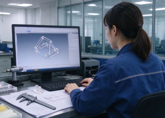
The first step is to verify the critical dimensions of the individual components. We recommend checking mounting interfaces, locating features, and any surfaces that determine the position of adjacent parts.
Next, the components should be assembled in the intended sequence. This helps identify whether a part can be installed without unnecessary force or interference.
After assembly, the visible relationships should be reviewed. These include panel alignment, joint gaps, flushness, and the position of control interfaces relative to surrounding trim.
We also recommend checking whether fastening changes the shape of the component. A panel may sit correctly before tightening but shift or deform once the final mounting load is applied.
Automotive Interior Prototype Assembly Checklist
| Inspection Item | What to Verify |
| Individual dimensions | Critical mounting and locating features |
| Installation sequence | Parts can be assembled without interference |
| Mounting alignment | Holes, pins, clips, and brackets align |
| Gap and flushness | Visible joints meet project requirements |
| Fastening condition | No unintended deformation or displacement |
| Cosmetic appearance | Finished surfaces remain acceptable after assembly |
| Revision control | Correct CAD and part revisions are used |
When a problem appears, we recommend documenting the exact location and assembly condition before modifying the design.
For example, an uneven bezel gap may result from the bezel geometry, the supporting housing, or the position of the display itself. Correcting the wrong component may create additional problems.
The objective of prototype assembly is to identify these relationships and support informed design revisions.
It is important to recognize the limits of this evaluation. Successful prototype assembly does not automatically demonstrate compliance with vehicle-level requirements for crashworthiness, long-term durability, flammability, environmental aging, or noise performance.
For automotive-specific qualification planning, the SAE J1717 Interior Automotive Plastic Part Testing document provides a relevant reference for the evaluation of individual interior plastic parts.
10. How Can a Direct Plastic Prototype Manufacturer Support Automotive Interior Development?
A direct plastic prototype manufacturer can help connect part manufacturing, surface finishing, and physical assembly during automotive interior development. We recommend involving the manufacturing team when the CAD design contains complex mounting interfaces, critical cosmetic surfaces, or several interacting components. Early communication helps clarify which requirements should be prioritized during prototype production.
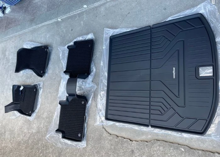
At UForProto, we manufacture plastic prototypes directly in our factory in Foshan, China. Our capabilities include CNC plastic machining, SLA/SLS 3D printing, vacuum casting, surface finishing, and complete prototype assembly.
For automotive interior projects, we can support the manufacturing of selected plastic housings, trim prototypes, bezels, covers, and related structural components.
We recommend that customers provide 3D CAD files, 2D drawings, material requirements, quantities, and details of critical cosmetic and assembly features.
If several components must fit together, information about the mating parts and intended assembly sequence can help us evaluate the manufacturing scope more accurately.
Our complete prototype services can support coordinated part manufacturing, suitable surface finishing, and physical assembly for projects within our capabilities.
We do not provide injection molding production or complete-machine functional testing. Automotive performance qualification and vehicle-level validation must be arranged separately according to the project’s requirements.
If you are developing automotive interior plastic prototypes, send your CAD files, drawings, and project requirements to info@uforproto.com for a manufacturing review and quotation.
Conclusion
Automotive interior plastic components must satisfy more than individual dimensional requirements. Housings, trim panels, and bezels need to integrate with neighboring structures while maintaining the intended appearance and assembly conditions. We recommend evaluating mounting features, locating interfaces, gap and flushness, surface finishing, and material suitability early in development. CNC plastic machining and other plastic prototyping processes can provide physical components for checking these relationships before production tooling. By combining appropriate manufacturing methods with dimensional inspection and prototype assembly, engineering teams can identify design conflicts, make targeted revisions, and develop more reliable automotive interior components while recognizing the additional testing required for production qualification.
FAQs
1. What Are the Most Common Automotive Interior Plastic Components?
Common examples include dashboard housings, instrument cluster frames, center console panels, door trim covers, display bezels, air vent housings, and control-interface components. Their design requirements vary according to function, appearance, and assembly conditions.
2. Which Plastics Are Commonly Used for Automotive Interior Prototypes?
ABS, PC, PMMA, PP, and POM may be considered for different prototype applications. We recommend selecting materials according to the intended evaluation rather than assuming every prototype must reproduce the complete performance of the production material.
3. Can CNC Machining Be Used for Automotive Interior Plastic Housings?
Yes. CNC plastic machining is suitable for many prototype housings, bezels, and structural components requiring defined geometry and accurate mounting interfaces. Its suitability depends on material, geometry, and the prototype’s intended purpose.
4. Why Are Gap and Flushness Important in Automotive Interior Trim?
Gap and flushness influence how adjacent interior parts align visually. We recommend measuring them at defined locations under consistent assembly conditions because individual part accuracy does not guarantee acceptable joint appearance.
5. Can 3D-Printed Clips Represent Production Automotive Trim Clips?
A 3D-printed clip can help evaluate geometry and installation space, but its mechanical behavior may differ from a production-molded clip. Retention force, fatigue resistance, and durability require appropriate material selection and separate validation.
6. What Should Engineers Check Before Approving an Automotive Interior Prototype?
We recommend checking critical dimensions, mounting alignment, assembly sequence, visible gaps, flushness, and cosmetic appearance. Engineers should also document unresolved issues and distinguish prototype fit approval from final automotive performance qualification.