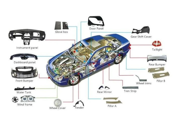

CNC Acrylic machining is widely used to produce transparent plastic prototypes, precision housings, and custom PMMA components. However, acrylic can crack, chip, overheat, or develop cloudy surfaces when machining conditions are poorly controlled. Achieving accurate dimensions and clear finishes requires more than selecting the right cutting tool. Material grade, workholding, toolpaths, residual stress, and finishing methods all influence the result. In this guide, we explain how CNC acrylic machining works, what causes common defects, and how engineers can improve part quality through practical material, design, and manufacturing decisions.
What Is CNC Acrylic Machining?
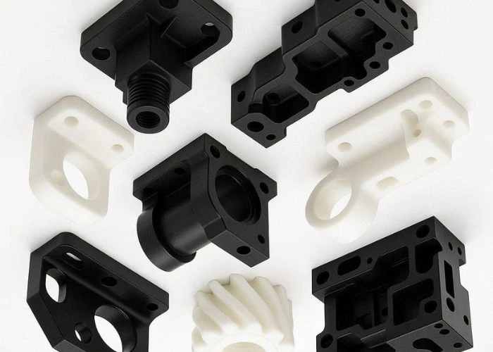
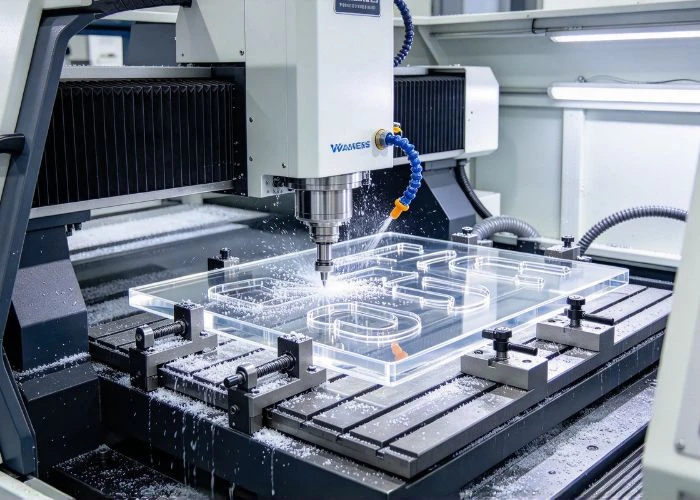
CNC acrylic machining is a subtractive manufacturing process that uses computer-controlled cutting tools to remove material from solid acrylic stock. Acrylic is also known as polymethyl methacrylate (PMMA). Unlike simple sheet cutting, precision CNC plastic machining can produce three-dimensional features, including pockets, stepped surfaces, mounting holes, and detailed component interfaces.
In plastic prototyping, we use CNC machining when a design requires physical geometry that can be measured, assembled, and visually evaluated. Typical projects include transparent device covers, display housings, inspection windows, and equipment components with precisely positioned features.
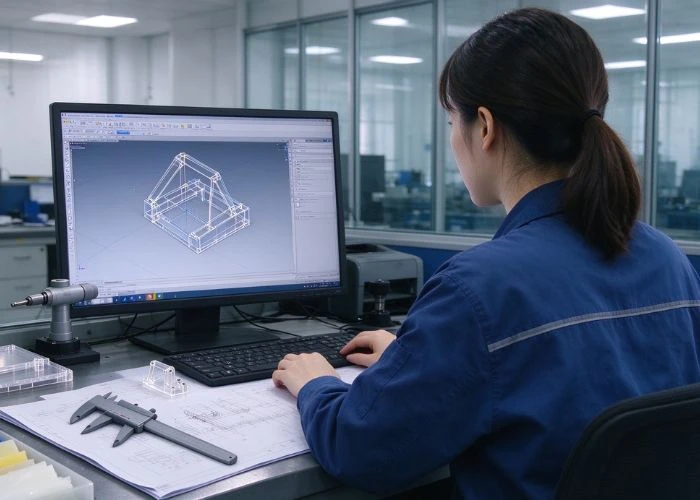
The process begins with a CAD model and an appropriate PMMA stock size. Machining operations then remove material in controlled stages. The final result depends on both the geometry and the condition of the material after cutting.
For example, a transparent acrylic housing may have accurate mounting holes but still be unacceptable if visible surfaces contain deep tool marks. We therefore treat dimensional accuracy and surface appearance as separate requirements during CNC acrylic machining.
Why Is Acrylic Suitable for CNC Plastic Prototyping?
Acrylic is frequently selected for plastic prototyping because it combines high visible-light transmission with rigidity, good surface appearance, and the ability to form detailed machined features. However, its advantages depend on the application. We recommend evaluating transparency, mechanical loading, and assembly conditions together rather than selecting PMMA solely for its glass-like appearance.
Clear PMMA can provide approximately 92% visible-light transmission under appropriate material and test conditions. This makes it useful for prototypes where engineers need to see internal structures or evaluate a transparent product appearance.
Its rigidity also helps maintain the intended shape of panels, covers, and certain housings. CNC machining can create accurate openings, recesses, and mating surfaces without requiring production tooling during early development.
However, PMMA is relatively brittle and sensitive to stress concentrations. It is not always suitable for parts exposed to high impact loads, aggressive chemicals, or repeated fastening stresses. A transparent prototype may demonstrate geometry successfully without representing the complete mechanical performance of the intended production component.
We commonly consider acrylic for transparent cosmetic prototypes, instrument covers, industrial inspection panels, and selected medical device housings. For these projects, the objective may be appearance evaluation, dimensional inspection, or assembly verification.
When comparing acrylic with other transparent engineering plastics, the final choice should reflect the actual operating conditions. Material selection is especially important when impact resistance or long-term mechanical performance matters more than visual clarity.
Cast vs Extruded Acrylic: Which Is Better for CNC Machining?
Cast and extruded acrylic are both PMMA, but their manufacturing histories influence how they behave during CNC machining. Differences in residual stress, thickness consistency, cutting response, and material cost can affect the final prototype. We generally consider cast acrylic for complex machined components, while recognizing that extruded acrylic may be appropriate for simpler applications.
Cast acrylic is produced through a casting process and is often preferred for detailed machining and polishing. Depending on the product grade, it may provide favorable machining behavior and a lower tendency toward certain stress-related defects.
Extruded acrylic is manufactured through continuous extrusion. It can offer more consistent sheet thickness and favorable material cost, particularly for straightforward panel applications. However, extrusion-related stresses may require additional attention during machining, bonding, or finishing.
Comparison Table — Cast vs Extruded Acrylic for CNC Machining
| Comparison | Cast Acrylic | Extruded Acrylic |
| Manufacturing process | Casting | Continuous extrusion |
| Machining suitability | Often preferred for detailed machining | Suitable for simpler parts with appropriate controls |
| Residual stress | Often lower, depending on grade | May contain greater processing-related stress |
| Thickness consistency | May vary more across sheet | Often more uniform |
| Surface finishing | Common choice for polished components | Requires attention to stress and finish response |
| Material cost | Often higher | Often lower |
| Prototype recommendation | Complex housings and clear machined parts | Simple panels and less demanding geometry |
For a transparent housing with deep pockets, multiple holes, and visible polished edges, cast PMMA is often our starting recommendation. For a flat cover with limited machining requirements, extruded material may be a reasonable alternative.
The decision should still be based on the actual stock specification. We recommend confirming sheet thickness, material grade, intended finishing, and the importance of stress resistance before purchasing the material.
For additional background on acrylic material selection, the Protolabs Network guide to acrylic CNC machining discusses cast and extruded grades alongside manufacturing considerations.
How Does CNC Acrylic Machining Work?
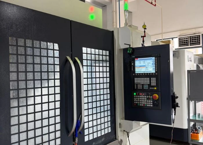
Successful CNC acrylic machining requires a controlled relationship between cutting forces, heat generation, chip evacuation, and workpiece support. Although the overall process resembles machining other engineering plastics, PMMA reacts differently to excessive friction and localized stress. We recommend treating tool selection, cutting conditions, and workholding as connected decisions rather than independent setup steps.
The process begins with reviewing the CAD model, drawing tolerances, and required surface finish. We identify thin sections, deep cavities, small holes, and surfaces that will remain visible after assembly.
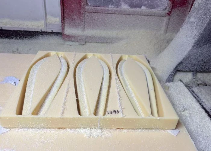
Next, the material is prepared and secured. The cutting program is developed according to the geometry, available tooling, and selected stock. Rough machining removes most of the material, while finishing operations establish critical dimensions and surfaces.
Tool Selection and Cutting Conditions for Acrylic
Sharp cutting edges are important because PMMA can generate excessive friction when a tool rubs rather than cuts. Polished-flute carbide cutters and suitable single-flute tools are frequently used in acrylic machining, although the optimal geometry depends on the operation.
Spindle speed should be considered together with feed rate, tool diameter, cutting depth, and chip load. Increasing spindle speed without adjusting the feed may increase rubbing and local heating rather than improve the finish.
We recommend evaluating the actual chips and machined surface during initial cuts. Clean chip formation, stable cutting behavior, and the absence of material smearing are useful indicators that the cutting conditions are moving in the right direction.
Workholding and Chip Removal During PMMA Machining
Acrylic must be supported securely without excessive clamping pressure. Concentrated loads can damage edges or introduce stress into thin sections. Flat panels may benefit from distributed support, while irregular housings may require fixtures matched to their geometry.
Chip evacuation is equally important. When chips remain near the cutting edge, they can be cut repeatedly or adhere to heated surfaces. This may increase friction and leave visible defects on transparent parts.
Air assistance or an appropriate material-compatible cooling strategy may help control chips and heat. Any coolant or cleaning fluid should be checked for compatibility with the selected PMMA grade because certain chemicals can contribute to environmental stress cracking.
We also recommend inspecting the part after releasing it from the fixture. A component that appears dimensionally stable while clamped may change slightly when restraint is removed.
What Are the Most Common CNC Acrylic Machining Problems and How Can You Prevent Them?
CNC acrylic machining problems often develop through interactions between material stress, cutting conditions, tool geometry, and part design. Cracking, melting, chipping, cloudy surfaces, and dimensional changes may appear similar at first, but their causes can be very different. We recommend identifying the defect mechanism before selecting a corrective action, especially for transparent plastic prototypes.
Why Does Acrylic Crack or Chip During CNC Machining?
Cracking and chipping are related but not identical problems. Chipping usually involves localized material loss near an edge, hole, or tool entry point. Cracking may extend farther into the component and can occur during machining, assembly, or subsequent handling.
PMMA is sensitive to concentrated stresses. Sharp internal corners, unsupported edges, aggressive tool engagement, and excessive clamping can all increase the likelihood of damage.
Drilling can be particularly challenging when the tool approaches the exit surface. Without adequate support, the remaining material may fracture as the drill breaks through.
We recommend reviewing the drill geometry, entry and exit conditions, backing support, and cutting sequence. Where appropriate, pilot holes or staged drilling can reduce sudden tool engagement.
If cracks appear after assembly rather than during machining, the investigation should also include fastener loading, residual stress, and chemical exposure. Replacing the cutting tool alone may not address the underlying problem.
What Causes Acrylic Melting and Tool Marks?
Acrylic can soften locally when cutting generates more heat than the process can remove. Excessive rubbing, inadequate chip evacuation, unsuitable feed conditions, and worn tools can all contribute to this problem.
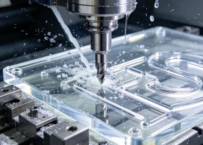
The visible result may include smeared material, adhered chips, rough edges, or irregular tool marks. These symptoms should not automatically be treated as a polishing problem.
We first examine whether the tool is cutting effectively. A sharp tool operating with a suitable chip load generally removes material more cleanly than a tool that repeatedly rubs the same surface.
Toolpath planning also matters. Excessive dwell time in one location can increase localized heating, while repeated cutting of trapped chips may damage the surface.
We recommend adjusting cutting conditions based on the actual machining response rather than relying on a universal spindle-speed value. The correct parameters depend on the cutter, machine, material grade, and feature geometry.
For broader thermal behavior across engineering plastics, our related article on Plastic Melting During CNC Machining provides additional context. The present guide focuses specifically on how thermal damage affects PMMA parts.
Why Do CNC Acrylic Parts Develop Cloudy or White Surfaces?
Cloudiness can result from several different surface or subsurface conditions. Fine machining marks scatter light, while microcracks or stress crazing may create a white or hazy appearance beneath the surface.
These defects require different responses. If the problem is limited to shallow tool marks, an appropriate finishing operation may improve transparency. If the material contains internal crazing, removing the outer surface may not solve the issue.
We recommend inspecting the affected area under suitable lighting and magnification before polishing. The defect’s depth, location, and relationship to mounting features can provide useful clues.
Chemical compatibility should also be considered. Some cleaning agents, adhesives, and solvents can contribute to stress crazing in loaded PMMA components.
A clear surface immediately after machining does not guarantee that the component will remain clear after bonding, cleaning, or assembly. We recommend evaluating the finished part under conditions relevant to its intended prototype use.
How Can Engineers Reduce Stress Cracking and Dimensional Changes?
Residual stress may originate from stock manufacturing, machining, workholding, or later assembly. Removing material can change the internal stress balance and cause a component to shift after it is released from the fixture.
For large or thin PMMA components, we recommend considering the order of material removal and the distribution of support. Balanced machining strategies and intermediate dimensional checks may help reveal distortion before final finishing.
Stress-relief annealing may be considered for selected components, particularly when later bonding or chemical exposure creates additional risks. However, temperature, duration, support, and cooling conditions must follow the material supplier’s recommendations.
Improper heat treatment can cause warping, dimensional changes, or surface damage. We therefore do not recommend applying a single annealing schedule to every acrylic grade or part thickness.
CNC Acrylic Machining Problems and Corrective Actions
| Problem | Possible Cause | Recommended Action |
| Edge cracking | Stress concentration or excessive cutting load | Review tool engagement, support, and geometry |
| Hole chipping | Unsupported drill exit or unsuitable tool | Improve backing and drilling sequence |
| Material smearing | Local overheating or rubbing | Adjust chip load and chip evacuation |
| Cloudy surface | Tool marks, microcracks, or stress | Identify the defect before finishing |
| Delayed crazing | Residual stress and chemical exposure | Review stock, assembly load, and chemical compatibility |
| Dimensional change | Stress release, heat, or inadequate support | Review machining sequence and inspection conditions |
The most effective correction depends on identifying the actual cause. We recommend recording when the defect first appears: during roughing, finishing, fixture release, polishing, or assembly.
This approach helps distinguish manufacturing problems from material or design limitations. It also reduces the risk of repeatedly remaking parts without addressing the underlying failure mechanism.
How Can Engineers Design CNC Acrylic Parts to Reduce Machining Risks?
Good CNC acrylic design balances functional requirements with PMMA’s sensitivity to stress, heat, and brittle fracture. Features that are acceptable in tougher engineering plastics may require modification when manufactured from acrylic. We recommend reviewing critical geometry before machining, particularly around mounting holes, internal corners, thin walls, and highly constrained assemblies.
Sharp internal corners can create local stress concentrations. Where the design allows, adding appropriate radii can improve the distribution of stress and provide clearance for the cutting tool.
The radius should reflect the actual feature size, loading conditions, and available tooling. We avoid treating a single minimum radius as suitable for every acrylic component.
Mounting holes also deserve attention. Holes positioned close to edges or sharp transitions can leave narrow sections that are vulnerable to cracking during machining or fastening.
We recommend reviewing edge distance, fastener clearance, contact pressure, and the expected tightening method. Where appropriate, clearance holes and load-distributing hardware may be preferable to highly stressed threads cut directly into PMMA.
Thin walls require another level of consideration. A wall may be strong enough in the final product but still deform under machining or clamping loads. Height, unsupported length, adjacent pockets, and tool access all influence the manufacturing risk.
We recommend identifying which walls are critical to assembly and which can be modified for manufacturability. In some cases, changing the machining sequence or temporary support strategy is more appropriate than increasing every wall thickness.
For additional guidance on feature accessibility, tolerances, and manufacturable geometry, see our design for manufacturability guide.
How Can CNC Acrylic Parts Achieve Clear and Smooth Surface Finishes?
Surface finishing is especially important in CNC acrylic machining because machining marks can become highly visible on transparent components. However, different projects require different levels of clarity. We recommend distinguishing between a smooth machined surface, a visually transparent cosmetic finish, and a surface with defined optical performance before selecting the finishing process.
An as-machined PMMA surface may show fine tool marks or a slightly frosted appearance. For a concealed structural feature, this may be acceptable. For a display cover or transparent product housing, additional finishing may be required.
Mechanical polishing uses controlled abrasive and polishing steps to reduce surface irregularities. The result depends on the initial surface condition, the geometry, and the finishing technique.
We recommend avoiding unnecessary material removal on critical mating surfaces. Polishing can change edge geometry and local dimensions, especially around small openings and thin features.
Flame polishing and solvent-based finishing are sometimes used in the acrylic industry, but both require careful process control. Heat or chemical exposure can introduce new stresses or defects, making them unsuitable for certain precision components.
For UForProto projects, the available finishing approach should be confirmed against the actual geometry and quality requirements rather than assuming every polishing method is offered or appropriate.
We also distinguish visual transparency from optical qualification. A component that looks clear to the eye does not automatically meet requirements for light transmission, haze, distortion, or other specified optical characteristics.
For projects with critical optical requirements, the relevant specifications and inspection methods should be established before manufacturing. This prevents cosmetic appearance from being mistaken for verified optical performance.
What Affects CNC Acrylic Machining Accuracy, Cost, and Lead Time?
CNC acrylic machining cost and lead time depend on more than part size or material volume. Complex geometry, tight tolerances, workholding requirements, finishing area, and inspection expectations can significantly influence manufacturing effort. We recommend reviewing these factors together because improving one requirement may increase the difficulty of meeting another.
A simple flat PMMA panel with a few holes generally requires less programming and machining effort than a transparent housing containing deep pockets, multiple setups, and thin structural features.
Material dimensions can also affect cost. A part that requires unusually thick or large stock may generate more waste and involve additional material preparation.
Tolerance requirements should be assigned according to function. Critical mounting holes or mating surfaces may justify tighter controls, while nonfunctional exterior dimensions may not require the same level of precision.
We recommend identifying these priorities directly on the engineering drawing. Applying unnecessarily tight tolerances to every dimension can increase inspection time, machining complexity, and the risk of rejected parts.
Surface finishing is another important cost driver. A large transparent cosmetic surface may require more finishing work than a small functional interface, even when both parts have similar machining times.
For purchasing teams, a useful quotation package should include the CAD model, 2D drawing, material preference, quantity, critical dimensions, visible surfaces, and required finish.
We also recommend identifying whether the part is intended for appearance review, assembly verification, or another development purpose. This helps prevent unnecessary manufacturing steps and supports a more accurate quotation.
How Can a Direct Manufacturer Support CNC Acrylic Prototyping?
A direct plastic prototype manufacturer can help connect design requirements with practical machining decisions. For CNC acrylic projects, we believe the most important starting point is understanding the purpose of the prototype. Transparency, critical dimensions, assembly interfaces, and acceptable cosmetic quality should be defined before the manufacturing process is finalized.
At UForProto, we manufacture plastic prototypes directly at our factory in Foshan, China. Our services include CNC plastic machining, SLA/SLS 3D printing, vacuum casting, surface finishing, and prototype assembly.
For CNC acrylic components, we can review the supplied geometry, material requirements, and critical features to determine a suitable manufacturing approach. This is particularly useful for transparent housings, inspection covers, display components, and multi-part prototypes.
We recommend providing both the CAD model and a drawing that identifies critical tolerances and cosmetic requirements. If the project includes assembly interfaces, mating-part information can help clarify which features require special attention.
For suitable projects, our complete prototype services can support coordinated plastic part manufacturing, finishing, and physical assembly. We do not provide injection molding production or complete-machine functional testing.
If you are developing custom CNC acrylic prototypes, send your CAD files, drawings, and requirements to info@uforproto.com. We can review the manufacturing scope and provide a quotation based on your project needs.
Conclusion
CNC acrylic machining can produce precise, transparent PMMA prototypes when material selection, cutting conditions, and finishing requirements are properly coordinated. Cast acrylic is often preferred for complex machined parts, but the final choice depends on geometry and project requirements. Cracking, melting, chipping, and cloudy surfaces should be investigated individually because each defect may have a different cause. We recommend combining thoughtful part design with appropriate tooling, workholding, chip evacuation, and inspection. Engineers should also distinguish visual clarity from verified optical performance. By addressing these factors early, development teams can reduce unnecessary revisions and obtain more reliable acrylic prototypes for dimensional, cosmetic, and assembly evaluation.
FAQs
1. Is Acrylic Easy to CNC Machine?
Acrylic is suitable for CNC machining, but it requires sharp tools, stable workholding, and appropriate cutting conditions. Its brittleness and sensitivity to heat make process control important.
2. Is Cast or Extruded Acrylic Better for CNC Machining?
Cast acrylic is often preferred for complex precision parts and polished prototypes. Extruded acrylic may be suitable for simpler panels, depending on stress, thickness, and finishing requirements.
3. Why Does Acrylic Crack During CNC Machining?
Cracking may result from excessive cutting forces, sharp internal corners, unsupported features, residual stress, or excessive clamping pressure. The actual cause should be identified before corrective action.
4. How Can You Prevent Acrylic From Melting During CNC Machining?
Use suitable cutting tools, maintain effective chip formation, and remove chips efficiently. Spindle speed, feed rate, cutting depth, and cooling strategy should be adjusted together.
5. Can CNC Machined Acrylic Be Made Transparent?
Yes. Appropriate machining and finishing can produce visually clear acrylic surfaces. However, optical-grade requirements need defined specifications and suitable inspection rather than visual judgment alone.
6. What Information Is Needed for a CNC Acrylic Prototype Quote?
We recommend providing 3D CAD files, 2D drawings, material requirements, quantity, critical tolerances, and surface finish expectations. Assembly information is helpful when components must fit together.