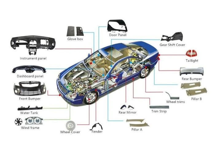

The machining definition refers to controlled material removal used to create parts with specified shapes, dimensions, and surface finishes. In plastic manufacturing, machining supports precision components, custom housings, and functional prototypes. Understanding different machining processes, material behavior, and design limitations helps engineers select suitable manufacturing methods while improving dimensional accuracy, surface quality, and production efficiency.
What Is Machining? Definition and Basic Principles
Machining is a subtractive manufacturing process in which material is removed from a workpiece to achieve a required geometry, dimensional tolerance, and surface finish. Conventional machining commonly uses cutting tools, while specialized machining processes may use other forms of controlled material removal. For plastic prototyping, we primarily rely on mechanical cutting operations such as milling, turning, drilling, and boring.
The machining definition is closely related to manufacturing, but the two terms are not interchangeable. Manufacturing describes the broader process of converting materials into products, while machining represents one group of manufacturing operations. Other manufacturing methods include additive manufacturing, casting, molding, and assembly. Understanding this distinction helps engineers avoid selecting a machining process simply because a part has complex geometry or requires high accuracy.
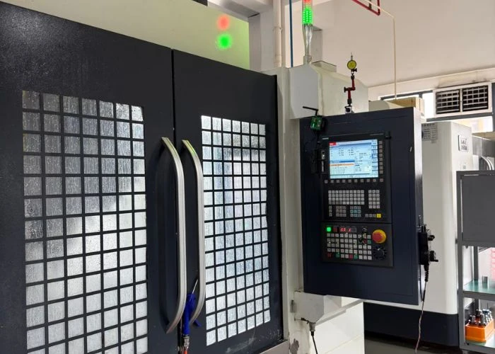
In conventional machining, the operator may control cutting movements manually. CNC machining uses programmed instructions to coordinate tool motion, spindle operation, and machining sequences. CNC technology improves repeatability and makes complex geometries more practical to manufacture, but the final result still depends on tool selection, workholding, material properties, machine condition, and process planning.
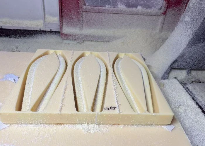
For engineers developing custom plastic components, machining is particularly valuable when parts must be produced directly from engineering-grade plastic stock. Unlike processes that create components layer by layer, CNC plastic machining removes material from solid sheets, rods, or blocks. This allows prototypes to retain many of the material characteristics associated with the selected stock, although actual part performance still depends on material grade, processing history, and geometry.
What Are the Main Types of Machining Processes?
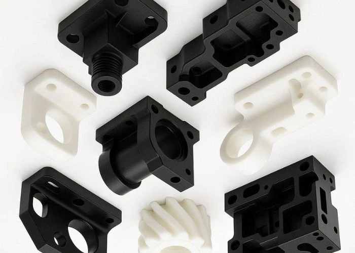
The main types of machining processes are distinguished by how the cutting tool and workpiece move relative to each other. Milling is commonly used for prismatic and complex-shaped components, turning is suited to rotational geometry, and drilling or boring creates and refines holes. These operations can be combined within one manufacturing sequence to produce plastic parts with different structural features and dimensional requirements.
CNC Milling and Routing
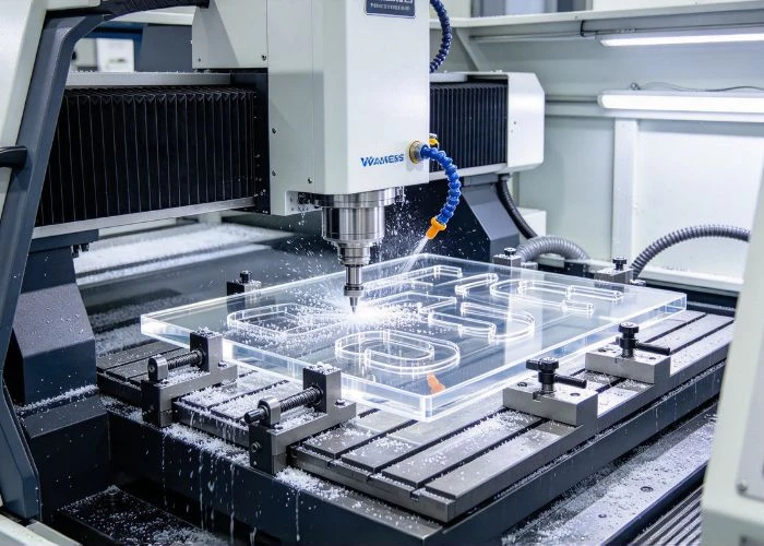
CNC milling removes material with a rotating cutting tool while the workpiece is held in a controlled position. Depending on machine configuration, the tool or workpiece moves along multiple axes to create pockets, slots, contours, mounting surfaces, and complex external profiles. For plastic prototyping, we commonly use milling to manufacture electronic housings, equipment covers, structural brackets, and other components with multiple geometric features.
Routing follows a similar material-removal principle but is commonly associated with high-speed cutting of sheet materials, panels, and relatively large profiles. The practical distinction between milling and routing depends on machine rigidity, spindle characteristics, tooling, and the intended application rather than a strict difference in cutting physics. For thin plastic panels or large covers, suitable routing equipment can provide an efficient manufacturing option.
When machining plastic housings, we pay particular attention to cutter access, internal corner radii, unsupported walls, and the order in which material is removed. Deep pockets and narrow features can increase cutting time and deformation risk. If a design requires inaccessible internal geometry, modifying the component structure or dividing the assembly into separate parts may be more practical than relying on additional machining operations.
CNC Turning
CNC turning is generally used for components with rotational geometry. The workpiece rotates while a cutting tool removes material to produce cylindrical surfaces, shoulders, grooves, tapers, and other concentric features. Common plastic applications include bushings, rollers, sleeves, spacers, and certain mechanical components where concentricity and diameter control are important.
Plastic turning requires careful control of cutting forces and workholding pressure. Long or slender components may deflect during machining, while thin-walled cylindrical parts can deform under excessive chuck pressure. We therefore consider material stiffness, unsupported length, wall thickness, and the required dimensional accuracy before selecting the turning approach.
Drilling, Boring, and Threading
Drilling creates holes using a rotating cutting tool, while boring enlarges or improves an existing hole when greater dimensional or geometric control is needed. Threading produces internal or external screw features through tapping, thread milling, or other suitable operations. In plastic components, these processes are frequently used for mounting holes, alignment features, fastener interfaces, and mechanical connections.
The selected hole-making method depends on diameter, depth, tolerance, material, and available tool access. Deep holes may create chip-removal difficulties, while holes located close to thin edges can increase the risk of distortion or cracking. For frequently assembled components, we also consider whether machined plastic threads or installed threaded inserts offer a more suitable connection for the intended loading and service conditions.
Other operations, including sawing, grinding, and finishing cuts, may be used to prepare raw stock or improve selected features. However, the most suitable machining process should always be determined by part geometry and manufacturing requirements rather than the availability of a particular machine.
How Does CNC Machining Work for Plastic Parts?
CNC machining converts digital part geometry into controlled cutting operations. Although the general workflow resembles metal machining, plastic components require additional attention to material condition, clamping force, cutting temperature, and dimensional stability. We normally evaluate the design, establish a machining sequence, manufacture the part, and inspect critical features before proceeding with any required finishing or physical assembly.
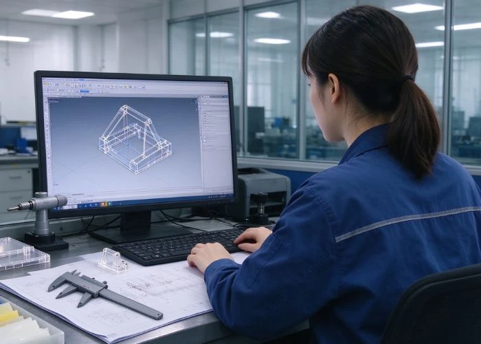
The process begins with a CAD model and relevant engineering drawings. We review the geometry to identify critical dimensions, cosmetic surfaces, mounting features, and possible manufacturing constraints. CAM software is then used to develop toolpaths and machining operations. Before cutting begins, the selected plastic stock must be checked for suitable dimensions, grade, condition, and sufficient material allowance.
Workholding is especially important for plastic components. A fixture must prevent unwanted movement without introducing excessive deformation. During machining, the cutting strategy should also consider heat generation, chip evacuation, tool sharpness, and the support remaining around thin features. Roughing and finishing operations may be separated when this helps control cutting forces or improve dimensional consistency.
After machining, we remove burrs and inspect the dimensions relevant to the component’s intended function. Some parts may require additional stabilization before final measurement, depending on the material and geometry. If painting, polishing, printing, or assembly is required, we also consider how those subsequent operations could affect the finished component.
For projects involving several manufacturing stages, our approach to plastic prototype manufacturing helps coordinate machining, finishing, and component fit rather than treating each operation as an isolated task.
Why Is Plastic Machining Different From Metal Machining?
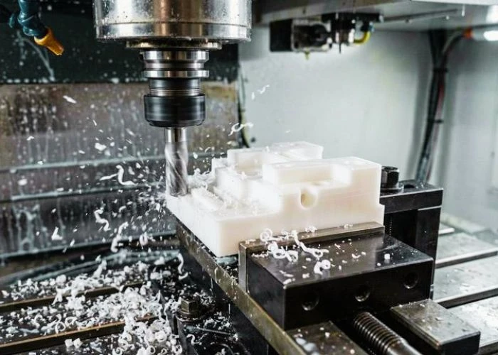
Plastic machining presents different engineering challenges because many polymers have lower stiffness, lower thermal conductivity, and higher thermal expansion than common machining metals. Some materials also exhibit significant viscoelastic behavior, meaning their deformation can depend on both load and time. These properties influence cutting conditions, fixture design, dimensional measurement, and the stability of the finished component.
Heat, Deformation, and Residual Stress
Heat generated during machining can affect plastic components differently from metal parts. Because many plastics dissipate heat less effectively, localized temperature increases may cause softening, surface smearing, or dimensional changes. The severity depends on the polymer, cutting speed, feed, tool geometry, chip formation, and machining duration. We therefore select cutting conditions according to the specific material instead of applying one universal parameter set.
Residual stress is another important consideration. Plastic sheets, rods, and blocks may contain internal stresses introduced during their production or previous processing. When machining removes material unevenly, the redistribution of those stresses can cause a component to bend, twist, or change dimensions. This is particularly relevant for large panels, thin covers, and parts with substantial differences in wall thickness.
For example, removing a deep cavity from one side of a plastic block may leave an uneven material distribution that increases distortion risk. Depending on the design, we may adjust the machining sequence, leave temporary support material, or consider intermediate stabilization. These measures must be selected according to the polymer and the actual part geometry; they cannot guarantee the elimination of all deformation.
Workholding and Dimensional Stability
Plastic components can deform under clamping loads that would be acceptable for many metal parts. A thin housing wall may bend when compressed, causing the tool to machine a temporarily distorted shape. After the fixture is released, elastic recovery can produce dimensional differences between the clamped and free states. We therefore consider contact area, support location, clamping pressure, and the sequence in which critical features are machined.
Dimensional stability also depends on environmental conditions. Temperature changes can affect measured dimensions, while moisture absorption can influence certain materials, especially some nylon grades. For precision plastic parts, engineers should identify the dimensions that directly affect assembly or performance and agree on realistic measurement conditions with the manufacturer.
The Thomasnet Guide to Plastic Machining also discusses how polymer properties influence machining behavior and process selection. These considerations are essential when moving from a general machining definition to the practical manufacturing of engineering plastic components.
Which Plastic Materials Are Suitable for CNC Machining?
Many thermoplastics and selected thermosetting materials can be machined, but their suitability depends on the required function, available stock form, geometry, and finishing requirements. We normally begin material selection by reviewing mechanical loads, operating temperature, dimensional needs, appearance, chemical exposure, and assembly conditions. Machinability is important, but it should not override the performance requirements of the finished component.
ABS is a common choice for appearance prototypes, housings, and consumer product components. It offers a useful balance of machinability, toughness, and finishing compatibility, making it suitable for many plastic prototyping applications. However, thin ABS features can still deform under unsuitable machining conditions, and painted surfaces may require additional preparation to achieve consistent appearance.
Polycarbonate (PC) is frequently considered for protective covers and structural housings where toughness and impact resistance are important. PMMA, commonly known as acrylic, is often preferred when transparency and visual appearance are priorities. Although both can be supplied as transparent stock, they behave differently during machining. PMMA is more vulnerable to brittle edge damage, while PC requires careful attention to machining stress and the intended finishing process.
POM, also called acetal, is widely used for precision mechanical parts, sliding components, and components requiring low friction. Nylon materials can offer useful wear resistance and toughness, but moisture sensitivity must be considered for dimensional applications. PP and PE may be suitable for chemically resistant or relatively flexible components, although their lower stiffness can make workholding and fine-feature machining more challenging.
Comparison Table: Common Plastics for CNC Machining
| Material | Typical Applications | Main Machining Considerations |
| ABS | Prototype housings, covers | Thin-wall support and finishing |
| PC | Protective housings, structural covers | Cutting stress and heat |
| PMMA | Transparent windows, display covers | Chipping, cracking, polishing |
| POM | Bushings, gears, precision components | Critical dimensions and workholding |
| PP | Chemical-resistant covers, flexible parts | Low stiffness and deformation |
| PA / Nylon | Wear components, mechanical parts | Moisture and dimensional variation |
| PEEK | High-performance mechanical parts | Material grade, tooling, cost |
The table provides general engineering guidance rather than universal material rankings. Actual machinability varies by resin grade, fillers, stock condition, tool selection, and part geometry. For material selection, we recommend evaluating the component’s intended service conditions before optimizing machining convenience or material price.
The Protolabs CNC Machining Materials Selection Guide provides additional information about matching material properties to mechanical, environmental, and cosmetic requirements.
How Do You Choose the Right Machining Process for Plastic Parts?
Choosing the correct machining process requires engineers to connect part geometry with material behavior, dimensional requirements, appearance, and manufacturing quantity. We do not recommend selecting a process solely from the material name or a general machining definition. Instead, we examine the features that must be produced, the surfaces that require control, and the practical limitations of the available manufacturing approach.
Choose Based on Part Geometry and Features
Part geometry is often the first factor in process selection. Components containing flat surfaces, pockets, ribs, mounting bosses, and irregular external contours are commonly suited to milling. Rotational components such as sleeves, rollers, and bushings are generally better candidates for turning. Parts requiring precise holes or threaded connections may need drilling, boring, or threading operations in addition to their primary machining process.
For example, a rectangular ABS enclosure with internal mounting bosses will normally require milling because its geometry includes pockets and non-rotational features. A POM spacer with a central bore and controlled outside diameter may be manufactured more efficiently by turning. A complex assembly may require several machining methods, followed by deburring, finishing, and physical fit checks.
Tool accessibility must also be evaluated. A CNC machine cannot automatically manufacture every feature represented in a CAD model. Deep narrow cavities, hidden undercuts, and inaccessible internal corners may require special setups, alternative tooling, or design changes. When such features are not essential to the intended function, simplifying the geometry can improve manufacturability and reduce unnecessary machining time.
Consider Tolerances, Surface Finish, and Production Quantity
Dimensional requirements should be assigned according to component function. A decorative housing surface may not need the same tolerance as a bearing seat or precision locating hole. Applying unnecessarily tight tolerances across an entire plastic component can increase machining time, inspection effort, and manufacturing risk without improving its practical performance. We recommend identifying critical dimensions and specifying realistic requirements for the remaining features.
Surface finish also affects the process plan. A transparent PMMA cover may require careful cutting and polishing, while an ABS cosmetic housing may be machined with sufficient finishing allowance before painting. For mating surfaces, the effect of coatings or other secondary operations must be considered during dimensional planning. These requirements should be discussed before machining rather than addressed only after the component is completed.
Production quantity changes the economic balance between processes. CNC machining is often practical for one-off prototypes and low-volume custom components because it avoids dedicated molding tooling. However, complex geometries, large material removal volumes, and extensive finishing can still make machining expensive. As quantities increase, engineers should compare the total cost and technical suitability of machining with other production methods.
Comparison Table: Choosing a Plastic Machining Process
| Part Requirement | Recommended Process | Main Consideration |
| Complex housing | CNC milling | Pockets, tool access |
| Cylindrical sleeve | CNC turning | Diameter and concentricity |
| Precision mounting hole | Drilling or boring | Hole geometry and tolerance |
| Threaded plastic feature | Tapping or thread milling | Strength and assembly cycles |
| Transparent plastic cover | Milling with suitable finishing | Surface quality and stress |
| Multi-part prototype | Combined machining and assembly | Fit and coordination |
When reviewing custom plastic parts, we use these factors to determine whether the proposed machining operations are appropriate for the geometry and intended application. The most efficient solution is not always the process with the fewest steps, but the one that achieves the required result with manageable manufacturing risk.
When Should You Choose CNC Machining Instead of 3D Printing or Vacuum Casting?
CNC machining, 3D printing, and vacuum casting are all useful in plastic prototype development, but they solve different manufacturing problems. CNC machining removes material from solid stock, 3D printing builds geometry additively, and vacuum casting reproduces parts using molds and suitable casting materials. The best choice depends on the required material properties, geometry, quantity, dimensional needs, appearance, and project schedule.
CNC machining is often preferred when a prototype must be made from a specified engineering plastic stock material or requires controlled machined interfaces. It is suitable for many structural components, precision housings, and mechanical parts. However, deeply enclosed channels, complex internal cavities, or inaccessible undercuts may be difficult or uneconomical to produce by machining alone.
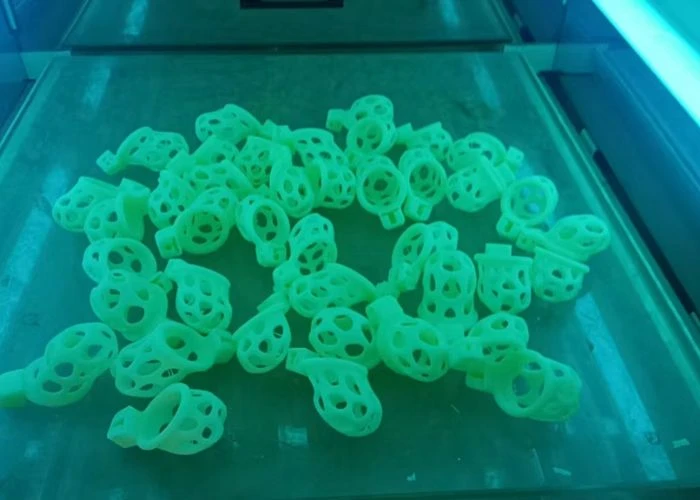
3D printing can be useful when geometry is complex, design iterations are frequent, or the project requires rapid physical evaluation. The available material properties and dimensional behavior depend on the printing technology and material system. For example, photopolymer-based printing and powder-bed nylon printing should not be treated as equivalent processes. Engineers must assess each method according to its actual material and manufacturing characteristics.
Vacuum casting can be practical when several similar appearance prototypes are required after a master pattern has been approved. It can reproduce complex exterior details and selected flexible or rigid components using appropriate casting resins. However, cast polyurethane properties are not necessarily identical to those of injection-molded engineering thermoplastics, and dimensional performance depends on the mold, geometry, and casting process.
Comparison Table: CNC Machining vs 3D Printing vs Vacuum Casting
| Factor | CNC Machining | 3D Printing | Vacuum Casting |
| Manufacturing Principle | Subtractive | Additive | Mold-based casting |
| Material Options | Engineering plastic stock | Process-specific print materials | Casting resins |
| Complex Internal Geometry | Limited by tool access | Often advantageous | Depends on mold design |
| Dimensional Requirements | Strong for accessible machined features | Depends on technology | Depends on mold and process |
| Typical Quantity | One-off and low volume | Prototypes and varied quantities | Repeated prototype copies |
| Main Limitation | Tool access and material removal | Material and process characteristics | Mold life and casting material properties |
For a deeper discussion of the transition between subtractive and additive processes, the Protolabs guide to moving between 3D printing and CNC machining for plastic parts provides useful examples of how material selection and geometry influence manufacturing decisions.
How Can UForProto Support Plastic Machining and Prototype Development?
At UForProto, we are a direct plastic prototype manufacturer specializing in CNC plastic machining and related prototype manufacturing processes. We work with product development teams to manufacture custom plastic housings, precision mechanical components, transparent covers, and multi-part prototypes. Our manufacturing approach begins with reviewing the design, material requirements, critical dimensions, and intended application before selecting the appropriate production strategy.
Our capabilities include CNC machining, 3D printing, vacuum casting, surface finishing, and physical prototype assembly. By coordinating these processes, we can support projects that require more than individual machined components. For example, a device prototype may include a CNC-machined ABS housing, a transparent PMMA window, painted exterior surfaces, and several internal mounting parts that must fit together during physical assembly.
We operate under an ISO 9001:2015 quality management system and review project-specific requirements according to the customer’s drawings and agreed inspection criteria. Our complete prototype services support coordinated manufacturing and physical assembly checks, helping engineers evaluate component appearance and fit before proceeding to the next development stage. These activities are distinct from complete product-level functional testing or regulatory qualification.
Whether a project requires a single precision plastic component or several assembled prototype parts, we focus on manufacturing feasibility, material suitability, dimensional requirements, and clear engineering communication. Our goal is to help engineers and purchasing teams select practical manufacturing solutions while reducing avoidable production risks.
Send your CAD files, engineering drawings, and plastic prototype requirements to info@uforproto.com for a manufacturing review and quotation.
Conclusion
Understanding the machining definition is the first step toward selecting a suitable manufacturing process for custom plastic parts. Milling, turning, drilling, and related operations each serve different geometric and functional requirements. Successful plastic machining also depends on material properties, cutting conditions, workholding, dimensional stability, and appropriate inspection methods. For engineers developing prototypes, CNC machining offers valuable access to engineering plastic stock and controlled machined features, while 3D printing and vacuum casting may be better suited to other design or quantity requirements. By evaluating geometry, material performance, surface finish, and manufacturing feasibility together, development teams can make more reliable process decisions.
FAQs
1. What Is the Simple Definition of Machining?
Machining is a manufacturing process that removes material from a workpiece to create a required shape, size, or surface finish. Common examples include milling, turning, and drilling. In CNC machining, programmed machine movements control the cutting operations.
2. What Are the Most Common Machining Processes?
The most common machining processes include milling, turning, drilling, boring, and threading. Milling is suitable for complex profiles and cavities, turning is commonly used for cylindrical components, and drilling or boring produces holes. Several processes may be combined to manufacture a single part.
3. Is CNC Machining Suitable for Plastic Materials?
Yes. CNC machining is suitable for many engineering plastics, including ABS, PC, PMMA, POM, PP, and nylon. However, cutting conditions, tooling, and workholding must be selected according to the material and geometry. Heat sensitivity, deformation, and dimensional stability require particular attention.
4. What Is the Difference Between CNC Milling and CNC Turning?
CNC milling generally uses a rotating cutting tool to remove material from a stationary or controlled-position workpiece. CNC turning typically rotates the workpiece while a cutting tool shapes its surface. Milling is commonly used for housings and irregular geometries, while turning is more suitable for cylindrical components.
5. Which Plastic Is Easiest to Machine?
There is no single easiest plastic for every machining application. ABS and POM are often considered relatively machinable for many common components, but actual results depend on grade, geometry, cutting conditions, and dimensional requirements. Materials such as PP, PMMA, and PC may require additional attention to flexibility, chipping, or stress.
6. How Do I Choose the Best Machining Process for a Plastic Prototype?
Start by evaluating the prototype’s geometry, material requirements, critical tolerances, surface finish, quantity, and intended use. Milling is often suitable for housings, turning for cylindrical parts, and drilling or threading for mounting features. If geometry is difficult to machine or multiple copies are required, compare CNC machining with 3D printing or vacuum casting before finalizing the manufacturing plan.