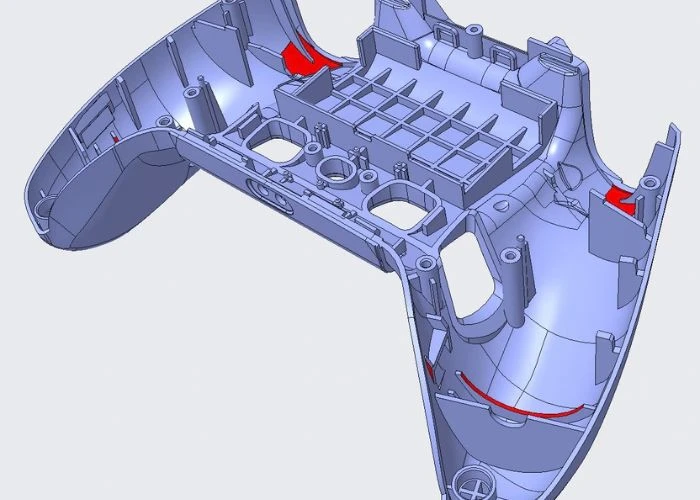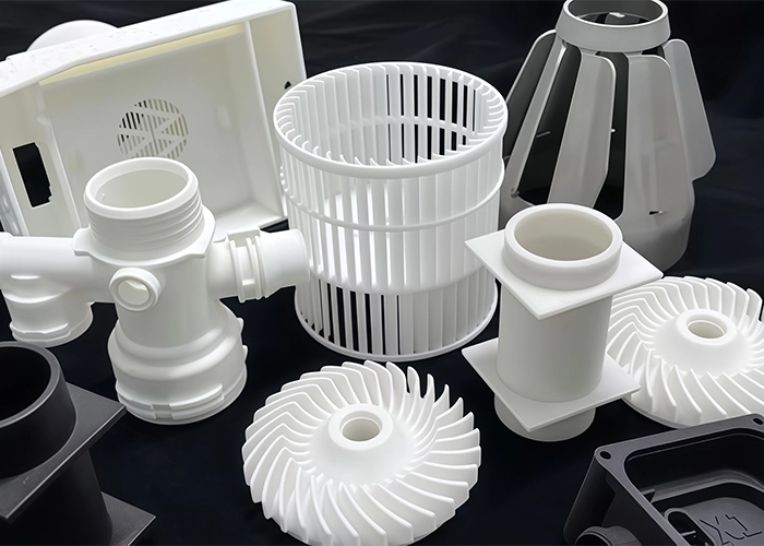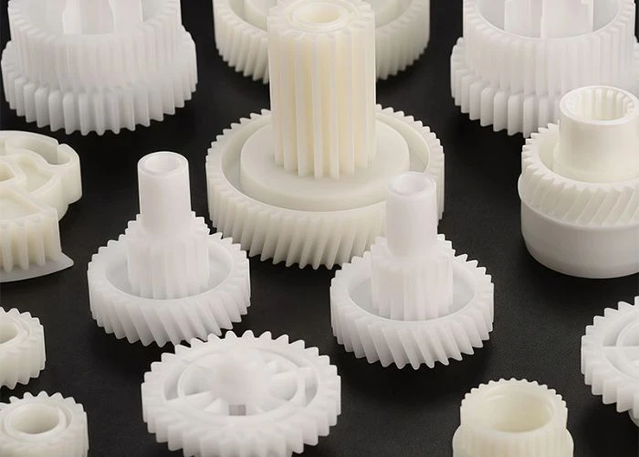

A 3D CAD file defines the shape of custom plastic parts, but it rarely tells a manufacturer everything required to quote and manufacture them correctly. In our plastic prototyping projects, I also need to understand which dimensions matter, what the prototype must verify, how the surface should look, and whether the part will later be assembled with other components. A professional RFQ therefore does more than request a price—it gives us enough engineering information to determine the right CNC plastic machining or prototype manufacturing route before production begins.
What Are Custom Plastic Parts in Prototype Manufacturing?
Custom plastic parts are non-standard components manufactured according to a customer’s CAD files, drawings, material requirements, and prototype objectives. Depending on the geometry, quantity, material, and intended evaluation, these parts may be produced through CNC plastic machining, SLA or SLS 3D printing, or vacuum casting. In custom plastic prototyping, the manufacturing route should reflect what engineers need to evaluate, whether that involves dimensional accuracy, appearance, mechanical behaviour, assembly, or a combination of these requirements.
A Good RFQ Defines More Than Part Geometry
When I receive an RFQ, the first question is not simply whether the CAD file can be opened. I need to understand what the customer expects the finished plastic part to achieve, because the same geometry can require different manufacturing decisions under different prototype objectives.
A STEP file tells me where the holes, ribs, pockets, walls, and exterior surfaces are located. However, it does not automatically tell me which hole controls assembly, which surface will remain visible after finishing, or whether a particular dimension is only a reference value.
This distinction matters during quotation. If I treat every feature as equally important, the manufacturing plan may include tighter control, more inspection, or more finishing work than the prototype actually needs.
The opposite problem also occurs. If a critical interface is not identified in the RFQ, the manufacturer may quote the part as a normal machined component without realizing that the feature controls a housing fit, moving mechanism, or final prototype assembly.
From a manufacturing perspective, I therefore separate RFQ information into two levels:
Part definition tells us what needs to be manufactured.
Project intent tells us what must be controlled during manufacturing.
This is why I consider a useful RFQ an engineering communication document rather than simply a request for pricing.
Start With the Right 3D CAD and 2D Drawing
3D CAD and 2D drawings serve different purposes during prototype quotation. In our workshop, I use the 3D model to understand how a part can be manufactured, while the 2D drawing defines the engineering requirements that cannot be reliably interpreted from geometry alone.
For CNC plastic machining, a solid 3D model allows me to evaluate much more than the external shape. Machining directions, deep cavities, internal features, tool access, setup requirements, and difficult workholding areas can all influence how the part should be produced.
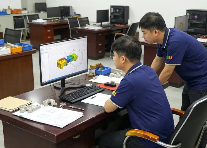
This is why two plastic parts with similar overall dimensions can have very different manufacturing requirements. A relatively open geometry may allow straightforward machining, while deep pockets, restricted tool access, or features distributed across several directions can require additional setups and machining time.
The 2D drawing becomes particularly important when critical tolerances, threads, fits, controlled hole positions, cosmetic surfaces, or specific inspection requirements are involved. These details tell us which features require additional attention rather than leaving the manufacturing team to treat every feature with the same priority.
For example, dimensions controlling assembly or positioning should be clearly distinguished from general reference dimensions. Visible surfaces can also be identified when their final appearance matters, while special inspection requirements should be linked to the features they are intended to verify.
A useful drawing therefore does not need to repeat every dimension already contained in the 3D model. What matters is making the manufacturing priorities clear enough that we can plan machining, finishing, and inspection around the features that actually affect the prototype result.
Tell the Manufacturer Which Dimensions Actually Matter
Tolerance information influences machining, inspection, setup, and cost, so it should reflect the engineering purpose of the part. In an RFQ for custom plastic parts, I prefer clearly identified critical dimensions rather than unnecessarily tight tolerances applied across the entire drawing.
For example, a housing may contain dozens of dimensions, but only several may determine whether the product assembles correctly. These could include locating holes, mating surfaces, button openings, mounting positions, or interfaces with customer-supplied components.
When these features are identified, I can plan machining and inspection around their actual importance. The rest of the part can then follow appropriate prototype manufacturing conditions rather than being treated as if every surface controls product function.
This becomes particularly important with plastic. Engineering plastics respond to cutting forces, heat, clamping, and part geometry differently from metals. A tolerance that is straightforward on a small rigid feature may become less practical on a large thin plastic housing.
From a quotation perspective, tighter requirements can mean additional machining control, different setup strategies, more measurement work, and sometimes a change in how the part should be manufactured.
That is why one of the most useful things an engineer can tell us is:
“These are the dimensions that affect my prototype result.”
This gives the manufacturer something much more useful than simply seeing the smallest tolerance somewhere on the drawing.
Define Material Requirements That Reflect the Prototype Purpose
Material information in an RFQ should tell us more than the general category of plastic. From a manufacturing perspective, the selected material can influence machining behavior, dimensional stability, surface preparation, finishing, and the way a prototype should be evaluated. This is why I first determine whether the material specification is already fixed or still open for prototype-stage discussion.
When the engineering team has already selected a material, the RFQ should identify it as precisely as the project requires. Specifying ABS, PC, PMMA, POM, PP, PA, PPS, Bakelite, or another engineering plastic gives us a much better basis for manufacturing review than simply stating “plastic.” If a particular grade, reinforcement, transparency level, or other material condition is important to the prototype, that information should also be included.
This level of detail matters because materials within the same general family do not always behave identically during CNC plastic machining. Their response to cutting heat, clamping, thin-wall geometry, polishing, or subsequent surface finishing can differ, so material information becomes part of the manufacturing plan rather than just a purchasing specification.
When the final material has not yet been selected, the RFQ can still provide useful engineering direction. If the material is still undecided, our plastic prototype material selection guide explains how to compare materials according to mechanical, environmental, and manufacturing requirements.Instead of choosing a familiar plastic simply to complete the specification, I recommend explaining which material characteristics are relevant to the current prototype. A transparent housing, a low-friction moving component, a rigid structural part, and an electrically insulating component clearly place different demands on the material, even before a specific grade is confirmed.
For plastic prototyping, this distinction is particularly useful because the prototype material should support the question being evaluated at that stage. An appearance prototype may place more emphasis on transparency or cosmetic quality, while an engineering part may require greater attention to rigidity, wear behavior, dimensional response, or machining characteristics.
The RFQ therefore does not need a finalized material specification in every situation, but it should avoid leaving the manufacturer with no engineering context. If the material is fixed, specify it clearly. If it is still under evaluation, explain the characteristics the prototype needs to represent. This gives us a much stronger basis for discussing a practical manufacturing option without making assumptions about the customer’s product requirements.
Quantity Can Change the Manufacturing Route
Quantity affects far more than unit price. When I review an RFQ for custom plastic parts, the required quantity helps determine whether CNC plastic machining, 3D printing, vacuum casting, or a combination of processes is the most practical route.
For a single engineering part, direct CNC machining may be the most efficient option because there is no need to create an intermediate mold or replication process. The project can move from approved CAD directly into machining.
When several identical or similar parts are needed, the calculation changes. It may still make sense to machine every part individually, but in some projects vacuum casting can provide a more efficient route once the master pattern has been prepared.
3D printing may also become useful when the geometry is complex or the design is still changing. In that case, speed of iteration can matter more than reproducing the exact characteristics of an engineering plastic.
This is why an RFQ that simply says “prototype parts” without a quantity is incomplete from a manufacturing perspective. I cannot evaluate the most efficient process without knowing whether the customer needs one part, five parts, or several prototype sets.
Quantity also helps us understand whether the project is likely to involve repeated assembly, customer demonstrations, internal testing, or several development teams using the same prototype.
For quotation purposes, I therefore treat quantity as a process-planning input, not just a number used to calculate price.
How Are Custom Plastic Parts Manufactured for Prototypes?
Custom plastic parts can be manufactured through different processes depending on the material, geometry, quantity, accuracy, and purpose of the prototype. I do not consider one manufacturing method suitable for every project. Instead, the process should be selected according to what the finished parts need to represent during product development.
CNC plastic machining is often suitable when engineers need actual engineering plastics, controlled dimensions, threads, mating features, or representative mechanical properties. SLA and SLS 3D printing are useful for rapid design iterations and complex geometry, while SLS can also produce durable nylon components. Vacuum casting becomes practical when several similar prototype parts are required with consistent appearance and production-like polyurethane properties.
For multi-part prototypes, these processes can also be combined rather than using the same manufacturing method for every component.
Define Surface Requirements Before Manufacturing Is Planned
Surface requirements are not simply a final step added after a plastic part has been machined. When I review an RFQ, I consider the required appearance together with geometry, material, and prototype purpose because the expected finish can influence how the part is machined, prepared, handled, and inspected throughout the project.
For example, a CNC-machined engineering component that will remain in its natural material condition does not require the same manufacturing approach as a cosmetic housing that will later be painted and silk screened. A transparent PMMA or PC part introduces another set of considerations because machining marks, hand finishing, polishing, and surface handling can directly affect the final visual result.
For this reason, descriptions such as “good surface finish” provide limited value in an RFQ. What helps us more is understanding the intended result: whether the part should retain its natural machined appearance, receive a matte or gloss painted finish, require polishing for transparency, or include secondary decoration such as silk screening, UV coating, or electroplating. If a color or appearance standard has already been defined, that reference should also be provided during quotation.
The location of the required finish is equally important. In a multi-part prototype, the front housing, side surfaces, internal structure, and mating areas do not necessarily serve the same purpose. A highly visible cosmetic face may require careful preparation and appearance control, while an internal surface may be more important for assembly than for visual quality.
This distinction can affect the work that happens before finishing. Areas intended for painting may require additional sanding and surface preparation, while transparent surfaces may need machining and polishing strategies that minimize visible defects. Mating or masked areas may also need to remain free of coating when additional thickness could interfere with assembly.
From an RFQ perspective, defining these requirements early allows us to evaluate CNC plastic machining, hand finishing, surface treatment, inspection, and assembly as one connected manufacturing sequence. Adding cosmetic requirements only after machining has been quoted can change more than the finishing cost—it may require us to reconsider work that should have been planned earlier.
Define What the Prototype Needs to Prove
A prototype is not manufactured simply to reproduce a CAD model. During an RFQ review, I want to understand what decision the engineering team expects to make after receiving the part. That information often has a greater influence on manufacturing priorities than adding more general specifications to the drawing.
Consider the same plastic housing at different stages of development. If the engineering team is reviewing its appearance, machining marks, edge transitions, visible gaps, transparency, and subsequent finishing may deserve greater attention. If the same housing is being used to confirm installation with a display, PCB, buttons, or another enclosure, the manufacturing focus moves toward locating features, mounting positions, mating surfaces, and the dimensions that control those relationships.
The difference becomes even more important when the prototype is intended to provide engineering information. In that situation, material condition, structural features, moving interfaces, or specific dimensions may need to represent the intended design more closely. A presentation model, by comparison, may place greater emphasis on overall appearance and clean assembly without requiring the same level of control on hidden, non-critical features.
This is why I prefer an RFQ to explain the engineering question behind the prototype rather than simply label it as “functional,” “cosmetic,” or “assembly.” Those labels are useful, but they can still leave room for interpretation. A short explanation of what needs to be checked gives us a much clearer basis for deciding where machining, finishing, and inspection effort should be concentrated.
For plastic prototyping, this is an important distinction: the most appropriate manufacturing plan is not necessarily the one that controls every feature to the highest possible level, but the one that produces reliable information for the current stage of product development.
Provide Enough Assembly Context to Understand Critical Interfaces
Once a custom plastic part interacts with other components, evaluating it in isolation can hide some of the most important manufacturing requirements. During RFQ review, I do not necessarily need the customer’s complete product design, but I do need enough context to understand the interfaces that determine whether the manufactured part will fit and assemble as intended.
For example, when machining a housing for a customer-supplied display, the housing model alone may show the opening and mounting structure, but it does not always explain which dimensions of the display are fixed, where clearance is acceptable, or which surfaces establish its final position. Seeing the relevant mating geometry allows us to understand the relationship rather than evaluating each dimension independently.
The same principle applies to housings, buttons, brackets, transparent windows, fasteners, and other components used in a prototype build. What matters is not the amount of assembly documentation provided, but whether the information reveals the interfaces that affect the part being manufactured. Depending on the project, a mating-part CAD model, a relevant section of the assembly, or the dimensions of a customer-supplied component may already provide enough context.
This context is particularly valuable in CNC plastic machining because a feature that appears ordinary on an isolated part can become critical once its relationship with another component is understood. A hole may control alignment, a shoulder may establish installation depth, or a small surface may determine the final gap between two housings. Identifying these relationships before machining gives us a better basis for planning how those features should be produced and checked.
Early assembly context also makes trial assembly more meaningful later in the project. Instead of waiting until all parts are finished to discover which interfaces actually matter, the manufacturing team can preserve those relationships from the beginning. This does not eliminate normal prototype adjustment, but it reduces avoidable assumptions between the customer’s design intent and the parts we manufacture.
Set Inspection Priorities Around the Decisions the Prototype Must Support
Inspection requirements for a prototype should be established from the same engineering priorities used to manufacture the part. In our work, I am less concerned with how many dimensions appear on an inspection report than with whether the measurements confirm the features that could change an engineering decision, assembly result, or subsequent design revision.
This is especially relevant in CNC plastic machining. A machined housing may have many measurable dimensions, but its engineering value could depend on only a few relationships: the position of a locating feature relative to a mounting surface, the spacing between two assembly points, or the gap created when it meets another component. Checking these relationships provides more useful information than treating every accessible dimension as equally significant.
The inspection method should also follow what is being evaluated. Dimensional measurement is appropriate when geometry controls fit or positioning, while visual inspection becomes more relevant when the prototype is being used to review painted surfaces, transparency, color consistency, or other cosmetic characteristics. Where several manufactured parts form an assembly, trial fitting can reveal cumulative relationships that individual measurements may not show clearly.
For this reason, an RFQ does not need to request the maximum possible inspection package by default. It should identify the characteristics that need evidence before the parts are accepted. This allows measurement, appearance review, and trial assembly to be planned around the engineering risk of the project rather than around the number of dimensions available to inspect.
Where RFQs Commonly Lose Manufacturing Clarity
Most RFQ problems are not caused by one missing field. They occur when the information provided is technically correct but does not describe the project well enough for manufacturing decisions to be made without assumptions. This is an important distinction because an RFQ can look complete on paper and still leave critical questions unresolved.
A CAD model, for example, may fully define geometry while leaving the importance of individual features unclear. A drawing may specify tight tolerances without showing which dimensions actually control assembly. A material name may be provided without identifying a grade that matters to the application. Likewise, a surface note may describe the desired appearance without distinguishing visible areas from interfaces where coating thickness could affect fit.
Another source of uncertainty is information that arrives in stages. If painting, supplied components, mating relationships, or special inspection requirements are introduced only after the original quotation, the issue is not simply that another service must be added. Those requirements may change work that was already planned upstream, including machining allowances, surface preparation, masking, dimensional control, or the sequence in which parts should be produced.
A strong RFQ therefore does not have to document everything about the product. It needs to remove uncertainty where an assumption could change manufacturing scope, cost, lead time, or the usefulness of the finished prototype. That is the level of completeness I look for when reviewing a project.
A Practical RFQ Framework for Custom Plastic Parts
At this point, the purpose of an RFQ should be clear: it is not to provide the largest possible package of technical documents, but to give the manufacturer enough information to establish the manufacturing scope without relying on assumptions. For custom plastic parts, I would organize that information around the following project inputs.
| Project Input | What Is Most Useful to Us | Manufacturing Decision It Supports |
| Part Definition | 3D CAD and relevant drawing information | Geometry review, machining access and setup planning |
| Controlled Features | Critical dimensions, fits, threads and interfaces | Machining and inspection priorities |
| Material Requirement | Specified grade or required prototype characteristics | Material suitability and process planning |
| Required Quantity | Parts per revision or prototype set | Process selection and batch planning |
| Appearance Requirement | Finish, visible areas and reference standard where applicable | Surface preparation and finishing scope |
| Prototype Objective | What the team needs to evaluate with the part | Manufacturing priorities and level of control |
| Assembly Context | Relevant mating geometry or supplied-component information | Interface review and trial assembly planning |
| Acceptance Requirement | Features or results that require verification | Inspection method and documentation scope |
| Project Timing | Required milestone or delivery expectation | Production scheduling and feasibility review |
How an RFQ Becomes a Manufacturing Plan
Once the RFQ contains enough engineering context, our next task is not to process each requirement independently. We need to see how geometry, material, quantity, appearance, inspection, and assembly conditions interact, because a decision in one area can change the practical solution in another.
A typical review starts with manufacturability, but it quickly moves beyond whether the geometry can physically be made. We look at where the part can be held, which features require access from different directions, how the selected plastic is likely to behave during machining, and whether later finishing or assembly creates requirements that need to be protected earlier in the process.
The manufacturing route develops from that combined review. Some parts are most appropriately produced directly through CNC plastic machining because material condition, machined features, or dimensional relationships are important. Other geometry may be better suited to SLA or SLS, while vacuum casting can become practical when a project requires multiple similar prototype parts. In a multi-part build, different processes can also be used within the same prototype rather than forcing every component through one method.
Only after that route is understood can machining, hand finishing, surface treatment, inspection, and trial assembly be arranged as a coherent sequence. This is the point where an RFQ stops being a collection of customer requirements and becomes a workable prototype manufacturing plan.
Conclusion
A useful RFQ for custom plastic parts does not need to contain every possible technical detail. It needs to clearly communicate the information that changes how the part should be manufactured, finished, inspected, and evaluated. The 3D CAD defines the geometry, while drawings identify critical requirements. Material and quantity influence the manufacturing route, surface specifications define cosmetic work, and assembly information helps protect important interfaces. Most importantly, the manufacturer should understand what the prototype is intended to validate. When these priorities are clear, quotation becomes more than a price calculation—it becomes the first stage of manufacturing planning.
FAQs
1. What Information Is Needed to Quote Custom Plastic Parts?
For most projects, I recommend providing 3D CAD files, material requirements, quantity, critical tolerances, surface finishing requirements, and any relevant assembly information. If the prototype has a specific evaluation purpose, include that as well.
2. Is a 3D CAD File Enough for a Custom Plastic Part Quote?
Sometimes. A simple part may be suitable for preliminary quotation from a 3D model alone. If the project includes critical tolerances, threads, cosmetic requirements, inspection needs, or assembly interfaces, additional drawings or specifications are usually helpful.
3. Do I Need to Specify the Plastic Material Before Requesting a Quote?
Not always. If the material is already defined, specify the exact plastic or grade where relevant. If it is not finalized, explain what the prototype needs to demonstrate, such as transparency, rigidity, wear resistance, heat resistance, or cosmetic quality.
4. Why Does Quantity Matter When Quoting Custom Plastic Parts?
Quantity affects more than unit price. It can influence whether CNC plastic machining, 3D printing, vacuum casting, or another manufacturing route is more practical for the project.
5. Should I Include Surface Finishing Requirements in the RFQ?
Yes, especially for cosmetic prototypes. Painting, polishing, silk screening, UV coating, electroplating, and other finishes can affect surface preparation, production planning, cost, and lead time.
6. Can I Request a Quote If My Prototype Requirements Are Not Fully Finalized?
Yes. Send the available CAD files, approximate quantity, known material or performance requirements, and the purpose of the prototype. We can then identify which missing details actually need clarification before manufacturing.