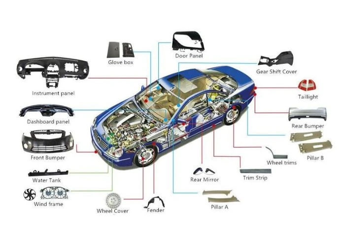

Understanding the different types of CNC machines is essential when selecting a manufacturing process for custom plastic parts. CNC milling, turning, and routing serve different purposes, while 3-axis, 4-axis, and 5-axis configurations influence tool access and machining flexibility. For plastic prototyping, the best choice depends on part geometry, material behavior, dimensional requirements, and surface quality rather than machine complexity alone. In this guide, we compare common CNC machine types and machining processes, explain their practical applications, and show how engineers can select suitable CNC plastic machining methods for prototype development.
What Are the Main Types of CNC Machines and Machining Processes?
The types of CNC machines can be classified by the manufacturing process they perform, their mechanical configuration, and the number of controlled axes. These classifications describe different aspects of a machine and should not be treated as interchangeable. We recommend understanding the machining operation first, then examining the equipment configuration needed to manufacture a particular component.
CNC, or Computer Numerical Control, uses programmed instructions to control machine movements and manufacturing operations. In subtractive machining, material is removed from a solid workpiece to produce the required geometry. CNC milling machines use rotating cutting tools, while CNC turning machines generally rotate the workpiece against a cutting tool. CNC routers commonly machine sheet materials and large profiles. Other computer-controlled equipment performs drilling, grinding, laser cutting, waterjet cutting, or electrical discharge machining. Although these technologies all use numerical control, their cutting mechanisms and material compatibility differ significantly.
For engineering plastics, milling, turning, and routing are among the most relevant processes. CNC drilling may also be performed on dedicated machines or as an operation within a machining center. Grinding is used for specialized finishing applications, but it is not automatically suitable for every polymer. Laser cutting can process certain plastic sheets, although thermal damage, edge quality, and potentially hazardous fumes must be considered. Waterjet cutting can produce profiles in suitable materials, but its suitability depends on the plastic and required edge quality. Electrical discharge machining requires an electrically conductive workpiece and is therefore not a conventional choice for most insulating engineering plastics.
Another important distinction is machine orientation. Vertical machining centers position the spindle vertically, while horizontal machining centers use a horizontal spindle arrangement. Gantry machines employ a bridge-like structure that can accommodate certain large workpieces. These configurations do not represent entirely different cutting principles. Instead, they influence machine travel, accessibility, workholding, and the kinds of parts that can be processed efficiently. When evaluating the types of CNC machines, we consider both the cutting process and the machine structure rather than relying on equipment names alone.
How Do CNC Milling, Turning, and Routing Work Differently?
Among the main types of CNC machining, milling, turning, and routing are particularly relevant to plastic components. Each process removes material differently and is best suited to particular geometries. We select among them by examining the dominant features of a part, the available stock material, and the requirements for dimensional control and surface finish.
CNC Milling for Complex Plastic Parts
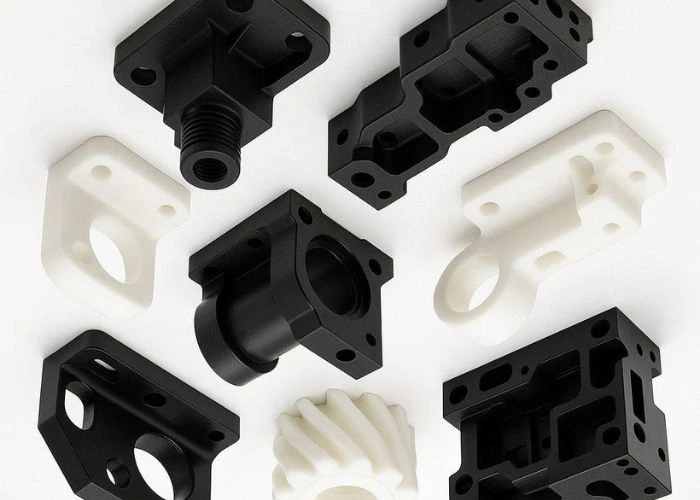
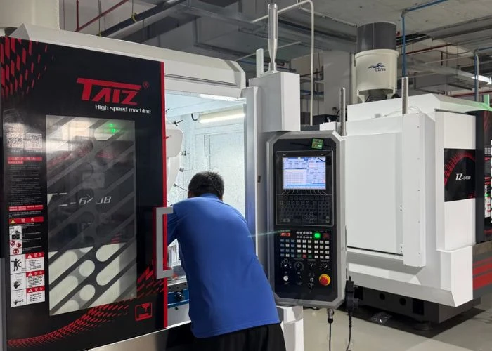
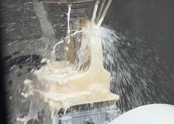
CNC milling removes material using a rotating cutting tool while the workpiece is secured in a fixture or on a machine table. The relative movement between the tool and workpiece creates pockets, slots, holes, external contours, and three-dimensional surfaces. For plastic prototyping, milling is especially useful for housings, brackets, mounting structures, and components with multiple functional features. We frequently consider this process when a part must be produced from a specified engineering plastic rather than a substitute material. Its flexibility makes milling one of the most important processes in CNC plastic machining.
However, milling capability is limited by tool access, part stiffness, and workholding. A deep narrow pocket may require a long cutting tool, which can increase deflection and reduce process stability. Thin plastic walls can move under cutting or clamping forces. Complex parts may also require several setups to expose different faces. We therefore review internal corners, pocket depth, minimum wall thickness, and datum locations before determining the machining sequence. A well-planned three-axis milling process can produce many sophisticated plastic components without requiring a more complex machine configuration.
CNC Turning for Cylindrical Plastic Components
CNC turning generally rotates the workpiece while a cutting tool removes material from its external or internal surfaces. This makes turning particularly suitable for components dominated by rotational geometry. Plastic bushings, sleeves, rollers, spacers, and cylindrical connectors are common examples. POM and nylon are frequently considered for mechanical components involving movement or wear, although the material grade must be selected according to the application. For suitable geometries, turning can produce consistent diameters and concentric features with an efficient machining sequence.
Not every cylindrical component can be completed by conventional turning alone. Flats, side holes, mounting slots, or complex non-rotational features may require secondary milling operations. Some turning centers incorporate driven tooling that can machine additional features without transferring the workpiece to a separate milling machine. Whether this is advantageous depends on the equipment available, the part geometry, and the required quantity. We assess the complete manufacturing sequence instead of assuming that every round component should be produced entirely on a lathe.
CNC Routing for Plastic Sheets and Large Panels
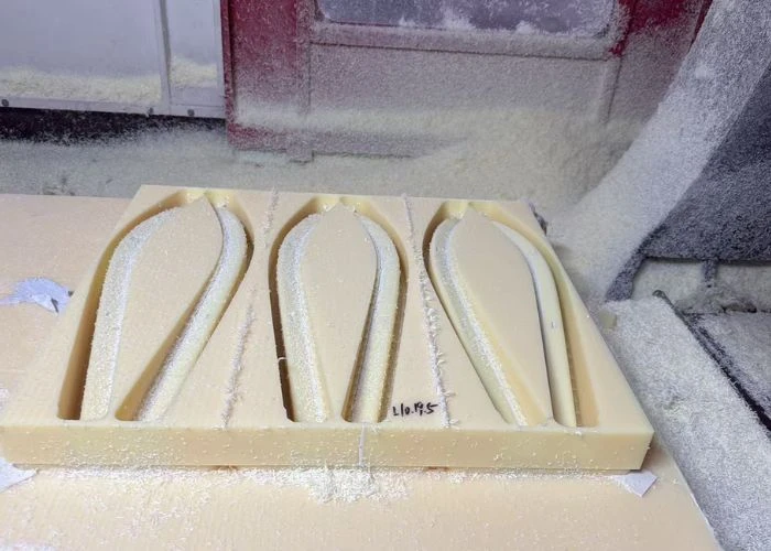
CNC routing commonly uses a high-speed rotating cutter to machine profiles, holes, and pockets in sheet materials. Many routers employ gantry-style structures and offer working areas suitable for relatively large panels. This makes routing useful for plastic covers, flat enclosures, equipment panels, and sheet-based components. When the original sheet surfaces already satisfy the design requirements, routing may preserve those surfaces while machining only the necessary outlines and openings. This can reduce material removal and simplify production for appropriate parts.
The distinction between CNC routing and milling is not simply that one process is accurate and the other is not. Industrial routers vary considerably in rigidity, spindle capability, motion control, and workholding systems. A rigid router may produce excellent results on suitable plastic components, while a poorly supported panel can deform even on sophisticated equipment. We evaluate the machine’s actual capability against the required tolerance, material thickness, and geometry. For large plastic sheets, effective support and clamping are often just as important as the selected machine type.
Comparison Table: CNC Milling vs Turning vs Routing
| Factor | CNC Milling | CNC Turning | CNC Routing |
| Cutting Principle | Rotating tool removes material | Rotating workpiece is cut | Rotating cutter machines profiles |
| Suitable Geometry | Pockets, housings, complex features | Cylindrical and rotational parts | Sheets, panels, flat profiles |
| Plastic Applications | ABS housings, PC brackets | POM bushings, nylon rollers | PMMA panels, plastic covers |
| Main Limitation | Tool access and workholding | Non-rotational geometry | Machine rigidity and part support |
| Selection Priority | Complex prismatic features | Rotational symmetry | Sheet-based geometry |
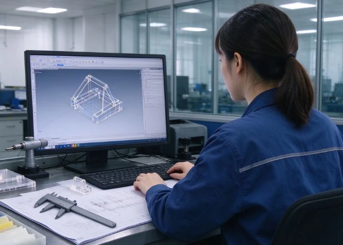
We use this comparison as an initial selection tool, not a substitute for reviewing the actual CAD model. A component may require more than one machining process, and the most efficient sequence depends on its critical features. For example, a plastic roller with cross-drilled holes may combine turning and drilling, while a large housing can require milling operations across several orientations. The objective is to choose a manufacturing route that produces the required features reliably without introducing unnecessary setups or equipment complexity.
What Is the Difference Between 3-Axis, 4-Axis, and 5-Axis CNC Machines?
The number of controlled axes is another way to distinguish the types of CNC machines. Axis configuration determines how the tool and workpiece can move relative to each other, influencing tool access and the number of setups required. We recommend evaluating axis count in relation to part geometry rather than assuming that additional axes automatically produce better components.
A typical three-axis milling machine controls movement along the X, Y, and Z linear axes. It can manufacture external profiles, pockets, slots, drilled features, and many three-dimensional surfaces accessible from the selected tool direction. If features appear on opposite sides of a component, the workpiece may need to be repositioned. Each setup introduces considerations related to locating accuracy, clamping pressure, and inspection references. Nevertheless, three-axis milling remains highly capable for many plastic housings, brackets, and structural components. Its effectiveness depends on thoughtful process planning and suitable workholding.
Four-axis milling adds a controlled rotary axis to the three linear axes. Depending on the machine configuration, the workpiece can rotate to expose additional faces or support certain rotary machining operations. This may reduce manual repositioning and improve access to features distributed around a component. However, the added axis does not remove all geometric limitations. Tool length, fixture interference, and the orientation of critical surfaces still affect manufacturability. We consider four-axis machining when the geometry benefits from controlled rotation, rather than selecting it solely because the equipment is more advanced.
Five-axis milling typically combines three linear axes with two rotational axes. Some machines use simultaneous five-axis motion, while others use indexed positioning, often called 3+2 machining. These configurations can improve access to angled surfaces, complex contours, and features that would otherwise require multiple setups. For certain components, reducing repositioning may improve consistency between related features. However, programming, fixturing, collision avoidance, and inspection can become more demanding. Five-axis machining should therefore be selected for a defined geometric or process advantage, not as a universal upgrade for every plastic prototype.
Comparison Table: 3-Axis vs 4-Axis vs 5-Axis CNC Machining
| Factor | 3-Axis CNC | 4-Axis CNC | 5-Axis CNC |
| Motion | Three linear axes | Three linear + one rotary | Three linear + two rotary |
| Suitable Features | Accessible pockets and contours | Features around multiple orientations | Complex angled and multi-face features |
| Setup Strategy | May require repositioning | Can reduce some repositioning | Can access more orientations in one setup |
| Programming | Generally simpler | Additional rotary planning | More complex toolpath planning |
| Best Selection Basis | Geometry and accessibility | Rotational positioning needs | Complex access or setup reduction |
The most appropriate axis configuration depends on the component, not the assumption that five axes always outperform three. A well-supported ABS housing with accessible features may be manufactured efficiently on a three-axis machine. A component with angled surfaces on several sides may benefit from indexed or simultaneous multi-axis machining. For plastic parts, we also consider how the chosen fixture supports the workpiece during cutting and whether the process maintains critical dimensions after unclamping. These factors can be more important than axis count alone.
Which Types of CNC Machines Are Best for Different Plastic Parts?
Selecting among the types of CNC machines becomes easier when we start with the component rather than the equipment. Plastic housings, mechanical components, large panels, and transparent parts have different manufacturing priorities. We examine their dominant geometry, functional interfaces, cosmetic requirements, and material characteristics before recommending a suitable machining process.
Plastic housings for medical devices, beauty equipment, consumer electronics, and industrial products frequently contain mounting bosses, internal pockets, ventilation features, and visible external surfaces. CNC milling is often suitable because it can produce these structures from solid plastic stock. However, a housing’s manufacturing plan depends on its size, wall thickness, and the accessibility of internal features. Large or thin-walled housings may require careful stock preparation and multiple machining stages to control deformation. When the prototype will be painted or assembled, we also consider how machining marks and dimensional interfaces will be affected by later operations.
Precision mechanical components often have different requirements. A POM bushing may primarily require accurate internal and external diameters, making turning an appropriate starting point. A plastic gear or mechanical bracket with complex profiles may require milling or a combination of operations. We pay particular attention to mating features, clearance, and the relationship between the component and surrounding parts. For moving assemblies, material selection and machining quality should be evaluated together. A dimensionally accurate component may still perform poorly if the selected polymer or fit is unsuitable for the intended mechanical conditions.
Large plastic panels and covers require careful consideration of machine travel, stock size, and workpiece support. CNC routing may be effective for flat profiles and openings, while milling may be preferred when thicker sections, precision pockets, or complex three-dimensional features are required. The decision is not based solely on overall dimensions. A large, flat panel with relatively simple features presents different manufacturing challenges from a deep industrial housing with internal ribs and multiple mounting surfaces. We evaluate how the part can be supported during material removal and whether it is likely to change shape after machining.
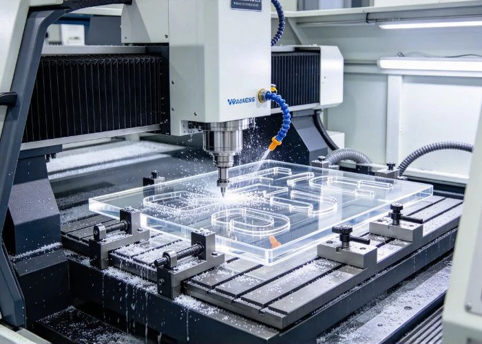
Transparent plastic components introduce additional considerations. PMMA and PC are commonly used for windows, covers, and display-related prototypes, but the machining method must be coordinated with the required optical appearance. CNC milling can create three-dimensional transparent components, while routing may be suitable for certain sheet-based parts. Neither process automatically produces an optically clear finished edge. Tool marks, internal stress, polishing methods, and surface protection all influence the result. We therefore separate dimensional acceptance criteria from cosmetic or optical requirements when planning transparent plastic prototypes.
Comparison Table: Plastic Parts and Suitable CNC Processes
| Plastic Part | Suitable CNC Process | Main Engineering Concern |
| Plastic housings | CNC milling | Wall thickness, tool access, assembly fit |
| Bushings and rollers | CNC turning | Diameter, concentricity, material grade |
| Large flat panels | CNC routing or milling | Support, machine travel, flatness |
| Transparent covers | CNC milling or routing | Surface marks, polishing, optical appearance |
| Multi-face structural parts | Multi-setup or multi-axis milling | Datum control and tool access |
| Mixed-geometry mechanical parts | Turning and milling | Feature relationships and setup accuracy |
For multi-component prototypes, we also consider how parts produced by different machining processes will fit together. A housing may be milled, a roller turned, and a flat panel routed, but all three must satisfy the same assembly requirements. Manufacturing each component independently without considering its interfaces can create unnecessary fitting problems. We therefore review the complete prototype structure and identify critical dimensions that should be controlled consistently across the different parts.
How Do Plastic Materials Affect CNC Machine and Process Selection?
Plastic material properties influence how a CNC process should be planned, but they rarely determine the machine type by themselves. The same polymer may be milled, turned, or routed depending on the part geometry. We evaluate material stiffness, thermal behavior, moisture response, and dimensional stability together with the intended features and machining conditions.
ABS is commonly used for prototype housings because it is available in machinable stock forms and can support a range of cosmetic finishing requirements. CNC milling is often appropriate for structural features and external surfaces. However, thin sections can deform if the workpiece is inadequately supported or excessive material is removed unevenly. We therefore consider stock condition, machining sequence, and fixture pressure when planning ABS components. If painting is required, the machining plan should also account for visible surface quality and the protection of critical mating features during finishing.
PC and PMMA are both relevant to transparent components, but they behave differently during machining and finishing. PC is generally valued for toughness, while PMMA is often selected for optical clarity and cosmetic appearance. Cutting conditions, tool condition, heat generation, and subsequent polishing can influence the final surface. We avoid treating these materials as interchangeable simply because both can be transparent. The correct machining strategy depends on the required geometry, surface appearance, mechanical properties, and the specific stock grade supplied.
POM is frequently used for components requiring dimensional consistency and mechanical movement, such as bushings, spacers, and sliding elements. Its relatively low friction and useful machining characteristics make it attractive for suitable mechanical applications. Nevertheless, thermal expansion and workholding still require attention. Turning may be efficient for rotational POM components, while milling is appropriate for brackets, plates, or complex profiles. The process is selected according to geometry, and the machining conditions are adjusted according to the material.
PP and PA66 introduce different considerations. PP can be relatively flexible, which may make thin or poorly supported features difficult to machine consistently. PA66 can absorb moisture, and its dimensions may change with environmental conditions. These behaviors do not make the materials unsuitable for CNC machining, but they influence stock preparation, fixture design, and inspection planning. We recommend defining the material grade and intended operating environment before establishing critical tolerances. Where dimensions are particularly important, measurement conditions and material conditioning may need to be specified.
The relationship between material properties and manufacturing feasibility is also central to design for manufacturability. We examine whether the selected plastic, wall thickness, internal features, and tolerance requirements can be manufactured together without creating unnecessary risk. The goal is not to redesign every component for the easiest possible machining operation. Instead, we aim to preserve the required function while identifying practical changes that improve machining access, dimensional stability, and manufacturing consistency.
How Do Different Types of CNC Machining Affect Accuracy, Cost, and Lead Time?
Different types of CNC machining can produce similar geometries through different manufacturing sequences. The selected process affects programming effort, fixture preparation, machining time, dimensional control, and secondary operations. We recommend evaluating these factors together because a faster cutting operation does not necessarily produce the lowest total cost or shortest project lead time.
Machining accuracy depends on more than the advertised positioning capability of the machine. Tool condition, fixture rigidity, temperature, workpiece deformation, and inspection methods all contribute to the final result. For plastic components, the difference between dimensions measured while clamped and after release can be particularly important. A machine may position its spindle precisely while the finished plastic part changes shape because of residual stress or insufficient support. We therefore focus on the accuracy of the delivered component under agreed inspection conditions rather than quoting a machine specification as a universal part tolerance.
Machining cost includes more than the time a cutting tool contacts the material. CAM programming, workholding, material preparation, tool changes, inspection, and secondary finishing can all contribute to the quotation. A complex housing may require multiple setups on a three-axis machine, while a suitable multi-axis process may reduce repositioning. However, the additional programming and equipment requirements of multi-axis machining may offset those savings for simpler parts. We compare the complete manufacturing sequence and the required quantity before deciding which approach is economical.
Consider two ABS housings of similar overall size. The first has accessible pockets, mounting holes, and relatively simple external surfaces. The second includes angled interfaces, deep internal features, and several critical relationships between different faces. Although both are described as plastic housings, their machining plans may differ substantially. The first could be manufactured efficiently using conventional milling setups, while the second may require more elaborate fixturing or multi-axis access. This illustrates why CNC machining quotations should reflect actual geometry rather than external dimensions alone.
Lead time should include engineering review, material procurement, programming, machining, inspection, and any required finishing or assembly. A part may leave the machine quickly but still require significant manual finishing before it is ready for a cosmetic review. Conversely, careful planning before machining can prevent repeated adjustments later. We recommend confirming when the delivery clock begins, whether material is available, and which operations are included in the quoted schedule. For prototype projects involving design revisions, clear approval milestones are particularly important.
How Should Engineers Choose the Right CNC Machining Process?
Choosing the right CNC machining process starts with the engineering requirements of the part. We do not begin by selecting the most advanced machine available. Instead, we evaluate geometry, material, critical dimensions, cosmetic expectations, quantity, and delivery needs, then determine which process can satisfy those requirements with manageable manufacturing risk.
The first consideration is part geometry. Rotational components may be suited to turning, while prismatic components with pockets and mounting features are commonly milled. Large flat panels may be candidates for routing. However, many components contain mixed features, and no single process description fully captures their manufacturing needs. We identify the dominant geometry and then examine secondary operations. This helps determine whether a combination of processes is more practical than attempting to complete every feature on one machine.
Next, we evaluate material and dimensional requirements. A thin-walled PP cover may need a different workholding strategy from a rigid POM block, even if both are machined on similar equipment. Critical datums, mating holes, flatness, and cosmetic surfaces should be clearly identified. We distinguish features that determine assembly function from those that are primarily visual or noncritical. This allows machining and inspection resources to be directed toward the requirements that matter most. It also helps prevent unnecessary cost from applying restrictive tolerances across the entire component.
Finally, we review the complete deliverable. If a prototype requires painting, printing, inserts, or mechanical assembly, those operations should be considered before machining begins. The manufacturing plan should account for finishing allowances, protected interfaces, and assembly relationships. When comparing suppliers, we recommend asking how the proposed CNC process will address the most difficult features rather than simply requesting a machine list. Engineers who also need help evaluating suppliers can refer to our CNC machining company selection guide once that article is published.
A practical selection process therefore follows a clear sequence: define the required geometry, confirm the material grade, identify critical dimensions, compare feasible machining methods, and review the complete finishing and inspection scope. This approach helps us select equipment according to engineering needs rather than marketing descriptions. The best CNC machining process is the one that can produce the required part reliably, at an appropriate cost, within the project schedule.
How Can CNC Plastic Machining Support Prototype Development?
CNC plastic machining plays an important role in prototype development because it allows engineers to manufacture components from specified engineering plastic stock without requiring production tooling. The process can support dimensional evaluation, assembly studies, cosmetic development, and selected mechanical assessments. We focus on matching the machining strategy and finishing requirements to the purpose of each prototype.
At UForProto, we are a direct plastic prototype manufacturer based in Foshan, China, not a trading company. We provide CNC plastic machining, 3D printing, vacuum casting, surface finishing, and prototype assembly. Our work includes plastic housings, precision structural components, cosmetic prototypes, and multi-part prototype builds for industries such as medical devices, beauty equipment, consumer electronics, personal care appliances, and industrial equipment. We focus on plastic prototype manufacturing and related finishing and assembly operations. We do not offer injection molding production or complete-machine functional testing.
For dimensional prototypes, we pay attention to mounting positions, mating features, material selection, and inspection references. Cosmetic prototypes may require additional sanding, painting, printing, or polishing to represent the intended appearance. Multi-component builds introduce another layer of complexity because individual parts must fit together after machining and finishing. Our complete prototype services help coordinate these manufacturing stages when the project requires more than individual machined parts. This integrated approach can reduce unnecessary handoffs between separate suppliers and improve communication about critical assembly interfaces.
We also recognize that CNC machining is not the ideal process for every prototype feature. Certain internal geometries, material combinations, or design iterations may be better suited to 3D printing or other prototype manufacturing methods. Our approach to plastic prototyping is to evaluate the design objective before recommending a manufacturing route. This allows us to consider the required material, geometry, surface appearance, quantity, and assembly needs together instead of promoting one process for every application.
For engineers and procurement teams planning a new project, we can review CAD files, drawings, material specifications, quantities, and surface requirements to assess manufacturing feasibility. If you need custom plastic prototype parts or a multi-component prototype build, send your project details to info@uforproto.com for a manufacturing review and quotation. Clearly identifying critical dimensions, cosmetic surfaces, and the intended evaluation purpose will help us recommend an appropriate production approach.
Conclusion
Understanding the types of CNC machines helps engineers select suitable processes for different plastic components. Milling is widely used for housings and complex features, turning suits rotational parts, and routing can be effective for sheet-based geometries. Machine axis configuration influences tool access and setup requirements, but more axes do not automatically guarantee better results. We recommend evaluating part geometry, plastic material properties, critical tolerances, surface requirements, and total manufacturing cost together. By matching CNC machining processes to actual engineering needs, manufacturers can improve prototype consistency, reduce avoidable machining risks, and support more efficient product development.
FAQs
1. What Are the Most Common Types of CNC Machines?
Common types of CNC machines include milling machines, lathes, routers, drilling machines, grinders, laser cutters, waterjet cutters, and EDM equipment. We consider milling, turning, and routing especially relevant to plastic prototyping. Each process has different strengths, and the appropriate choice depends on the part geometry, material, and manufacturing requirements.
2. What Is the Difference Between CNC Milling and CNC Turning?
CNC milling generally uses a rotating cutting tool to remove material from a secured workpiece. CNC turning usually rotates the workpiece against a cutting tool. We recommend milling for housings, pockets, and complex non-rotational features, while turning is often more suitable for bushings, rollers, and cylindrical components.
3. Which Type of CNC Machine Is Best for Plastic Parts?
There is no single best CNC machine for every plastic part. We typically consider milling for complex housings and structural components, turning for rotational parts, and routing for suitable sheets and panels. The final selection depends on material properties, geometry, dimensional requirements, and the available machine and fixture capabilities.
4. Is 5-Axis CNC Machining Better Than 3-Axis CNC Machining?
Not necessarily. Five-axis machining can improve tool access and reduce setups for certain complex geometries, but three-axis machining is effective for many plastic components. We recommend choosing the axis configuration that meets the design requirements without unnecessary programming, fixturing, or manufacturing cost.
5. Can CNC Machines Process ABS, PC, PMMA, and POM?
Yes. CNC machines can process ABS, PC, PMMA, POM, and many other engineering plastics when suitable tooling and machining conditions are used. We evaluate the specific material grade, geometry, heat sensitivity, workholding requirements, and dimensional expectations before selecting the machining approach.
6. How Do I Choose a CNC Machining Process for Prototyping?
We recommend starting with the CAD geometry, specified material, critical tolerances, quantity, and required surface finish. A manufacturing review can then determine whether milling, turning, routing, or a combination of processes is appropriate. For multi-part prototypes, assembly requirements should also be considered before machining begins.