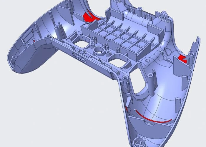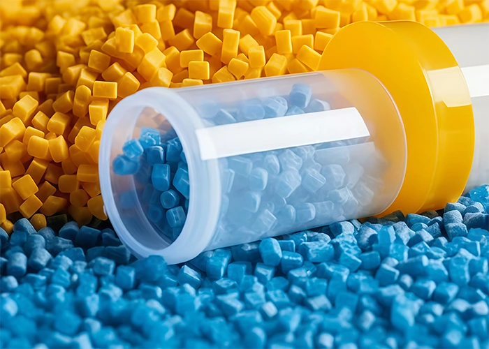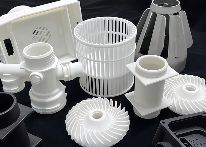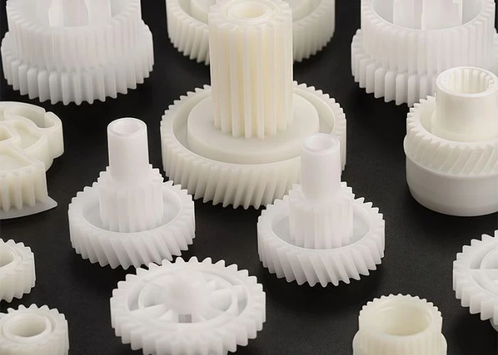

A CAD model can look completely correct on screen and still create unexpected challenges once manufacturing begins. Design for Manufacturability (DFM) helps identify these issues before plastic prototyping moves into production. From difficult machining access and unsupported features to unnecessary tolerances and finishing requirements, practical DFM allows engineers to preserve the purpose of a prototype while making CNC plastic machining and other manufacturing processes more predictable and efficient.
Design for Manufacturability in Plastic Prototyping
In prototype manufacturing, DFM is not simply about making a part easier for the factory to produce. I see it as a way to connect the original engineering intent with the realities of machining, finishing, inspection, and assembly before manufacturing begins.
A prototype normally exists to answer specific development questions. One project may need to evaluate movement between components, another may focus on enclosure assembly, and another may require a production-like cosmetic appearance. Because those objectives are different, the DFM decisions should also be different.
From our manufacturing perspective at UForProto, I therefore avoid treating DFM as a fixed checklist that forces every CAD model into the same rules. The more useful approach is to identify which features are essential to the prototype and which features can be adjusted without changing what the engineering team needs to learn.
This distinction is particularly important in plastic prototyping. A geometric change that looks minor in CAD may influence how a plastic part is held during machining, how the cutter reaches a feature, how the surface is finished, or how several parts fit together later.
Design Features That Increase Plastic Prototype Manufacturing Difficulty
Some CAD features create much more manufacturing effort than their appearance suggests. During DFM review, I pay particular attention to geometry that affects cutting-tool access, part rigidity, machining direction, and the number of operations required to complete a plastic prototype.
Thin Walls, Deep Cavities, and Difficult-to-Reach Features
Thin walls are a good example of the difference between digital geometry and physical manufacturing. During CNC plastic machining, a thin or unsupported section may move under cutting forces, making it more difficult to maintain stable dimensions and surface conditions.
This does not mean that every thin wall should be redesigned. Its importance depends on the material, wall height, surrounding support, part size, and what the prototype needs to verify. Competitor CNC DFM guidance similarly warns that thin plastic features can flex or warp during and after machining.
Deep pockets create a different problem. As cavity depth increases, longer tools may be required. A longer cutting tool is generally less rigid, and access becomes more restrictive, particularly when narrow openings or tall surrounding walls limit the machining path. Protolabs also highlights deep, narrow pockets and features located beside tall walls as common CNC manufacturability concerns.

For DFM, the practical question is therefore not simply whether the cavity can be machined. I want to know whether the current depth and access are necessary for the prototype objective, or whether a small structural adjustment can reduce manufacturing difficulty without changing the engineering evaluation.
Internal Corners, Undercuts, and Complex Geometry
CNC milling tools are round, so a true sharp internal corner cannot be produced directly with a standard rotating cutter. Smaller internal radii normally require smaller tools, which can increase machining time or place additional limitations on pocket depth. This relationship between cutter size, radius, and machining access is also emphasized in CNC DFM guidance from Protolabs.
Undercuts and hidden features create another type of challenge. Many of these structures can still be manufactured, but they may require a different machining direction, additional setups, special tools, or secondary operations.
That distinction matters in prototype DFM:
A feature that can be manufactured is not necessarily a feature that can be manufactured efficiently.
When I review a complex feature, I therefore consider its engineering value before recommending a change. If the geometry directly affects product function, we plan manufacturing around it. If it has little influence on the current prototype objective, simplifying the feature may provide a more efficient route.
Tolerances Should Match the Purpose of the Prototype
Tolerance decisions are part of DFM because every additional dimensional requirement influences how a part is machined and inspected. For a prototype, I prefer to focus dimensional control on the features that influence the engineering result rather than automatically tightening every dimension.
An enclosure mounting interface, locating feature, moving connection, or mating surface may directly affect whether a prototype provides useful feedback. These dimensions deserve more attention because a dimensional deviation could change the conclusion of the evaluation.
Other dimensions may primarily define general shape or non-functional surfaces. Applying the same tolerance level to these features can increase machining and inspection work while providing little additional engineering value.
This is especially relevant to CNC plastic machining, because plastics respond differently to machining forces and heat than metals. Fictiv’s CNC DFM guidance likewise notes that plastic parts are more affected by thermal deformation and that narrow tolerances can be more challenging than on metal parts.
The DFM objective is therefore to identify where dimensional control changes prototype performance and where additional precision only adds manufacturing effort.
DFM Changes With the Prototype Manufacturing Process
A design that is difficult for one manufacturing process may be straightforward for another. For this reason, DFM should not be separated from process selection. In our plastic prototyping projects, CNC machining, 3D printing, and vacuum casting each introduce different manufacturing considerations.
For CNC plastic machining, I pay close attention to cutting-tool access, internal radii, deep pockets, unsupported walls, machining direction, and how the part can be held securely during different operations. Current CNC DFM guidance from Fictiv similarly identifies tool accessibility and fixturing as important manufacturability considerations.
With 3D printing, tool access becomes much less important, but the manufacturing questions change. Build orientation, support structures, fragile details, printed surface condition, and subsequent sanding or painting may become more relevant.
For vacuum casting, I consider how the master pattern will be manufactured, how the silicone mold will reproduce the geometry, whether delicate features can remain stable, and how the cast parts will be removed and finished.
There is therefore no universal DFM rule that works equally well for every prototype process. The manufacturing method must be considered together with the CAD geometry and the purpose of the prototype.
Practical DFM Decisions That Make Parts Easier to Manufacture
Good DFM does not require removing every complex feature from a product. Instead, I focus on reducing manufacturing effort where it does not contribute to prototype value and preserving complexity where it is needed for meaningful engineering evaluation.
Simplify Geometry Without Losing Prototype Function
One of the most useful DFM questions is whether a difficult feature is necessary at the current development stage. A complex pocket, very small internal corner, hidden recess, or decorative detail may have a clear engineering purpose—or it may simply remain from an earlier CAD concept.
If the feature affects fit, movement, function, or another important validation target, I would not remove it simply to make machining easier. Instead, the manufacturing process should be planned to preserve that feature.
However, when complexity adds manufacturing work without providing useful prototype information, a simplified geometry may help the engineering team obtain the same development feedback more efficiently.
The goal is not the simplest possible part. It is the simplest manufacturing route that still preserves the purpose of the prototype.
Consider Machining, Inspection, Finishing, and Assembly Together
Manufacturability does not end when a CNC machine finishes cutting. A prototype may still require dimensional inspection, hand finishing, painting, silk screening, trial assembly, or integration with other components.
For this reason, I also look at whether important dimensions can be measured conveniently, whether cosmetic areas can be prepared for finishing, and whether there is enough access to install fasteners or mating components during prototype assembly.
A feature that is easy to machine but difficult to inspect or assemble may simply move the manufacturing problem to a later stage.
This broader manufacturing view is particularly useful for multi-part plastic prototyping projects, where the final engineering value depends on the complete prototype rather than on any single machined component.
DFM Checklist Before Sending Your CAD Files
A short manufacturability review before submitting CAD data can identify many issues that otherwise appear during quoting or production. I recommend focusing first on features that directly influence machining access, part stability, inspection, finishing, and assembly rather than attempting to redesign the entire product.
| DFM Check | What to Review | Manufacturing Impact |
| Wall Thickness | Thin or unsupported areas | Part stability during machining |
| Internal Corners | Sharp or very small internal radii | Cutter size and accessibility |
| Deep Features | Deep pockets and narrow cavities | Tool reach and machining stability |
| Undercuts | Hidden or restricted geometry | Additional setups or special tools |
| Tolerances | Critical vs. general dimensions | Machining and inspection effort |
| Tool Access | Clearance around machined features | Process feasibility |
| Inspection Access | Ability to measure critical features | Verification efficiency |
| Assembly Features | Mating and installation areas | Trial assembly and fit evaluation |
| Surface Requirements | Cosmetic areas and finish expectations | Post-processing planning |
Many competitor DFM guides use similar manufacturability checks because problems such as deep pockets, sharp internal corners, tight tolerances, and inaccessible features directly affect CNC machining effort.
DFM Review Before Prototype Manufacturing
DFM provides the most value before machining or printing begins. Once the manufacturing route has been confirmed and parts are already in production, design changes become more disruptive. Early review allows engineering intent and manufacturing constraints to be discussed while adjustments are still relatively easy to make.
At UForProto, we are a direct plastic prototype manufacturer, so our DFM review is based on how the part will actually move through the manufacturing process. When customers send CAD files for custom plastic parts, we normally consider the intended material, quantity, dimensional priorities, surface requirements, and whether the parts will later be assembled into a complete prototype.
Turning DFM Feedback Into Practical Manufacturing Solutions
Useful DFM feedback should not stop at saying that a feature is difficult to manufacture. Engineers need to know what creates the difficulty, whether it affects the prototype objective, and what practical alternatives are available.
For example, if a pocket requires a difficult machining approach, the solution may involve adjusting the geometry, changing the machining direction, splitting the component, or selecting another prototype process. The correct answer depends on the engineering purpose of that feature.
This is why I treat DFM as a manufacturing conversation rather than a pass-or-fail design check. The objective is to find a route that keeps the required engineering information while making the prototype practical to manufacture.
Better DFM Creates More Useful Prototypes
The real value of DFM becomes clear when the finished prototype reaches the engineering team. A manufacturable design moves through production more predictably, but it should also preserve the features needed for meaningful testing, evaluation, and development decisions.
The goal is therefore broader than reducing machining effort. Good Design for Manufacturability helps shorten the distance between CAD data and a useful physical prototype by addressing manufacturing concerns before they become production problems.
For product development teams, this means fewer avoidable revisions and more time spent evaluating the product itself. The prototype can move into assembly, testing, customer review, or the next design iteration with clearer engineering information.
Conclusion
Design for Manufacturability (DFM) helps bridge the gap between a CAD model and a prototype that can be manufactured efficiently and evaluated effectively. For plastic prototyping, good DFM means more than simplifying geometry. It requires understanding which features are critical to the prototype, how tolerances affect manufacturing effort, whether machining and inspection access are practical, and how the selected process influences the final result. By considering these factors before production begins, engineers can reduce avoidable manufacturing difficulties while preserving the information the prototype is meant to provide. If you are preparing a new plastic prototype project, you can send your CAD files and project requirements to UForProto for manufacturing review and quotation.
FAQs
1. What Is Design for Manufacturability (DFM)?
Design for Manufacturability (DFM) is the practice of reviewing a product design against real manufacturing conditions so potential production difficulties can be identified before manufacturing begins.
2. Why Is DFM Important for Plastic Prototyping?
DFM helps identify geometry, tolerance, machining-access, finishing, and assembly issues before they create unnecessary manufacturing work or prototype revisions.
3. When Should a DFM Review Be Performed?
A DFM review is most useful after CAD geometry is sufficiently developed but before prototype manufacturing begins, when adjustments can still be made efficiently.
4. What Are Common DFM Issues in CNC Plastic Machining?
Common issues include thin unsupported walls, deep narrow cavities, sharp internal corners, difficult tool access, undercuts, and unnecessarily tight tolerances.
5. Does DFM Mean I Need to Change My Product Design?
No. DFM should preserve the engineering purpose of the prototype. Design changes are only considered when they improve manufacturability without affecting the required evaluation.
6. What Should I Provide for a Prototype DFM Review?
Provide 3D CAD files together with material preferences, quantities, critical tolerances, surface finishing requirements, and assembly information when applicable.