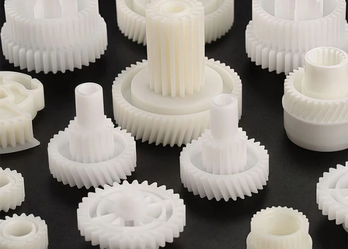

Large Plastic Prototype Machining is not simply conventional CNC machining applied to a bigger workpiece. As part size increases, material removal, support conditions, datum relationships, multiple setups, and final assembly begin to interact. If sectioned manufacturing is required, bonding introduces another dimensional chain that must also be controlled. In our plastic prototyping projects, we therefore plan large-part CNC manufacturing around the final assembled geometry rather than treating machining, bonding, finishing, and inspection as separate operations.
Why Large Plastic Parts Become More Difficult to Control During CNC Machining
The first challenge is not simply that the workpiece occupies more machine space. A large plastic blank can change its mechanical condition significantly as material is removed. Long unsupported areas, large cavities, thin walls, and uneven material distribution can make the part behave differently near the end of machining than it did during the first setup.
A typical example is a large housing machined from a thick plastic block. At the beginning, the stock itself provides considerable stiffness. Once the internal cavity is opened and most of the material is removed, the remaining structure may consist mainly of broad walls, ribs, and narrow connecting areas. If critical mounting faces or interfaces are finished too early, they are being machined while the workpiece still has a structural condition that no longer exists in the finished part.
The Manufacturing Solution: Control Support and Material Removal Together
For this reason, our machining plan starts by identifying where the largest material removal will occur and how the remaining structure will be supported at each important stage. Instead of machining every accessible feature directly to its final condition, we may establish the basic geometry through rough machining first, retain material where additional support is useful, and complete sensitive surfaces or interfaces later in the process.
The fixture is planned with the same logic. For a large panel, clamping only around the perimeter may prevent the blank from shifting but still leave the cutting area inadequately supported. We therefore consider the distance between the cutter and support points, the rigidity remaining after roughing, and whether the fixture is holding the part naturally rather than forcing a flexible surface flat.
This approach is consistent with established plastic-machining guidance: stress-relieved stock, controlled material removal, suitable support, and intermediate stress-relief measures can become important when substantial volumes are removed from engineering plastics.
What Must Still Be Controlled?
The new risk is assuming that a part is correct simply because it measures correctly while clamped. Excessive fixture pressure can temporarily suppress movement and create a geometry that changes after release. For large CNC plastic machining, important dimensions should therefore be evaluated under a condition that represents the finished part as closely as practical, especially after major material removal has been completed.
How We Control Long-Distance Features and Multiple CNC Setups
As part size increases, dimensional accuracy becomes less about whether one hole or pocket is correct and more about whether features separated across the part remain correctly related. This is particularly important for large housings, covers, and structural prototypes that must eventually fit a frame, display, internal assembly, or customer-supplied component.
Consider a housing with mounting interfaces near both ends. Each interface could satisfy its local dimensions while the distance or orientation between them still prevents proper assembly. This problem becomes more difficult when the part needs to be turned, repositioned, or machined from several directions because every new setup introduces another reference relationship into the process.
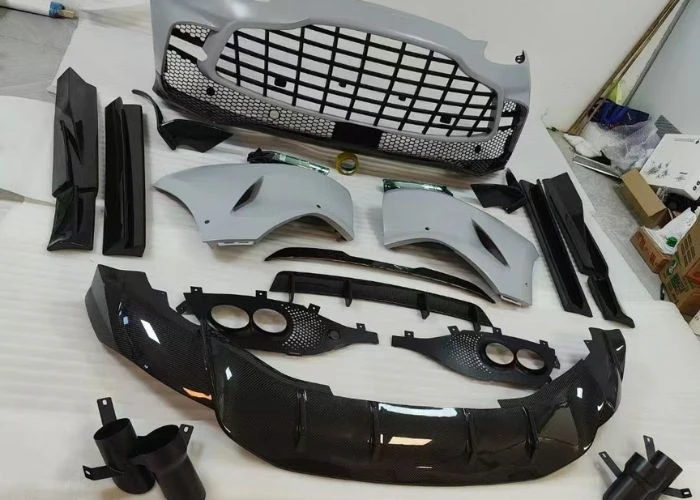
The Manufacturing Solution: Build the Process Around Functional Datums
Before programming the complete machining sequence, we identify which features actually work together in the final prototype. Those relationships determine which references should be established early, which surfaces can be used for repositioning, and which critical features should be completed after the main structural machining has stabilized.
This is different from selecting a datum only because it is convenient for the first setup. A useful datum strategy must survive the manufacturing route. When the workpiece is turned, the next setup needs a reliable way to recover the relationship already established on the opposite side. Where several distant interfaces matter to assembly, we also plan inspection around their common relationship rather than checking each feature only as an isolated dimension.
This is especially important in Large Plastic Prototype Machining because a small angular or positional change near one datum can become much more significant when evaluated at a feature located far away.
What Must Still Be Controlled?
A more sophisticated datum plan does not mean every dimension needs a tight tolerance. Over-controlling non-critical geometry can make manufacturing unnecessarily difficult without improving prototype evaluation. The priority should remain on the dimensions and relationships that determine fit, alignment, mounting, and the engineering purpose of the prototype.
When Should a Large Plastic Prototype Be Divided Into Machined Sections?
One-piece machining is usually attractive because it avoids bonded joints and keeps more geometry within a continuous machining reference. However, once the part becomes large or structurally awkward, insisting on one-piece manufacturing can make workholding, internal access, material removal, turning, surface preparation, and even handling unnecessarily difficult.
This is why we do not make the one-piece versus sectioned decision from machine travel alone. A CAD model may physically fit inside a CNC machine but still be a poor one-piece candidate if the workpiece cannot be supported properly after roughing or if important internal geometry becomes difficult to reach and finish.
The Manufacturing Solution: Section the Part Around the Complete Process
When sectioning offers a more controllable route, we determine the split based on more than the dimensions of each machine setup. The joint must work for machining, locating, bonding, finishing, and final assembly at the same time.
For cosmetic prototypes, natural edges, structural transitions, steps, or less visible areas are often worth evaluating because they can reduce the amount of joint finishing required. However, placing a joint where it is visually convenient is not enough. If that location crosses a critical mounting interface or provides poor locating geometry, the finishing advantage may be outweighed by the dimensional risk created during assembly.
A good sectioning strategy therefore answers two questions together: Does dividing the part make CNC manufacturing more stable, and can those sections be reconstructed into the required final geometry with predictable control?
Large-prototype manufacturing guidance reaches a similar conclusion: sectioning should be engineered around joint location, alignment features, finishing, and final inspection rather than treated merely as a workaround for machine-envelope limitations.
What Must Still Be Controlled?
Once the part is divided, we have exchanged one large machining problem for several smaller machining tasks plus a new assembly problem. The next manufacturing strategy must therefore control how the individual sections come back together. This is where bonding accuracy becomes just as important as CNC accuracy.
How Do We Prevent Bonding From Changing the Final Dimensions?
This is one of the most easily underestimated problems in sectioned Large Plastic Prototype Machining. Three sections can all pass CNC inspection individually and still produce an incorrect complete prototype after bonding. The reason is that assembly creates a new dimensional chain that did not exist when the sections were measured separately.
Assume a long housing is divided into three CNC-machined sections. Each section carries its own manufacturing variation. During bonding, joint clearance, adhesive thickness, locating accuracy, and angular alignment are added to those existing variations. A small positional change at one joint may have little local effect but can create a much larger displacement at the far end of a long assembly.
The Manufacturing Solution: Make Alignment Part of the Joint Design
We therefore avoid treating bonding as a purely manual finishing operation. Where final geometry matters, the joint should provide a controlled method of locating the sections. Depending on the structure, this can involve locating steps, reference faces, pins, overlap features, internal supports, or a dedicated bonding fixture.
The objective is not simply to make the joint stronger. The more important manufacturing purpose is to prevent the sections from finding an uncontrolled position while the adhesive cures. For a large housing, the bonding fixture should control the relationships that matter to the finished prototype without forcing flexible panels into a temporary shape that changes after release.
This is why individual-part accuracy and final assembly accuracy must be treated separately. CNC machining establishes the sections; bonding establishes the relationship between them.
What Must Still Be Controlled?
The completed assembly should not move directly from bonding into extensive cosmetic finishing. Filler and sanding can make a misaligned joint look smooth, but they cannot restore an incorrect mounting position, overall width, or distant interface relationship.
For that reason, we prefer to confirm important overall dimensions and assembly relationships after bonding and before the joint is extensively filled, sanded, or painted. Once the geometry is accepted, finishing can concentrate on appearance without being used to hide an underlying dimensional problem.
How Should the Final Large Prototype Be Inspected?
The final challenge is deciding what “correct” means after all manufacturing stages are complete. Large prototypes can pass many individual dimensional checks while still failing the engineering purpose of the project. This is particularly true for sectioned assemblies, because the geometry that matters to the customer may only exist after bonding.
For one-piece CNC plastic machining, we inspect the critical local features but also consider long-distance relationships such as mounting positions, mating boundaries, and alignment between features located on different regions of the part. A collection of correct local measurements does not automatically prove that the complete structure will fit its mating assembly.
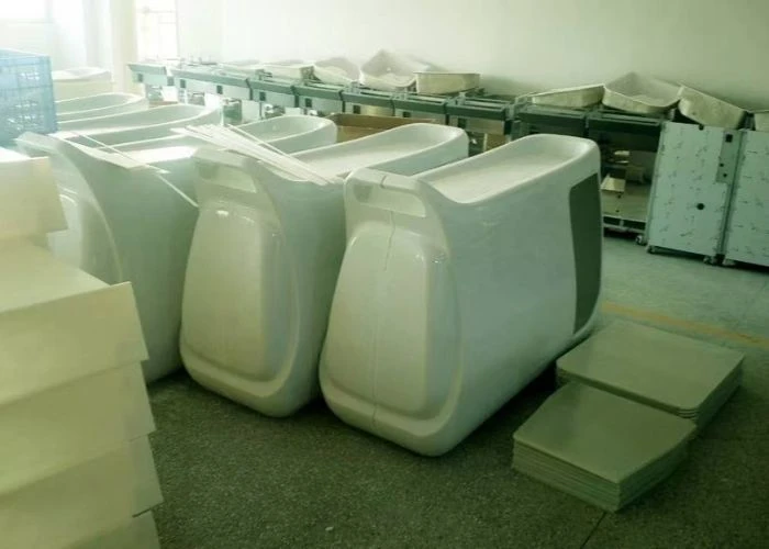
The Manufacturing Solution: Inspect According to the Manufacturing Route
For sectioned prototypes, we use two different levels of dimensional control. Before bonding, important section dimensions and joint interfaces are checked to confirm that the components are suitable for assembly. After bonding, the complete structure is evaluated again for the dimensions and relationships that only exist at assembly level.
This second inspection is not a duplicate of the first. It answers different engineering questions: whether the overall size is correct, whether distant interfaces remain aligned, whether bonding has introduced angular or positional change, and whether the prototype fits the mating components for which it was manufactured.
The inspection plan should therefore follow the dimensional chain all the way from CNC machining to the final assembled prototype. That is the condition the customer ultimately needs to evaluate.
How UForProto Approaches Large Plastic Prototype Machining
As a direct plastic prototype manufacturer, we do not evaluate a large project by asking only whether our CNC machine can accommodate the CAD model. We first determine which manufacturing route gives us the most practical control over the final prototype, including machining stability, sectioning where necessary, bonding relationships, surface finishing, and final dimensional verification.
If one-piece machining is appropriate, we plan support, material removal, machining sequence, and functional datums around the complete structure. If sectioned manufacturing provides a better route, we extend that planning into split locations, locating features, bonding fixtures, post-bonding inspection, and joint finishing. In both cases, the objective remains the same: the manufacturing process must protect the geometry the customer actually needs to evaluate.
Our CNC plastic machining, hand finishing, surface finishing, and prototype assembly capabilities allow us to manage these stages as one connected plastic prototyping workflow. This is especially important for large housings and multi-section prototypes, where the quality of the final result depends on more than the accuracy of each individual machined part.
Conclusion
Large plastic prototyping projects require a different CNC strategy as part size increases. Workholding, datum control, machining sequence, and sectioning decisions all affect the final result. If a part must be split, bonding and alignment also become part of dimensional control. For this reason, we evaluate large prototypes as complete manufacturing projects rather than isolated CNC parts. If you are developing a large plastic prototype, you can send us your CAD files and project requirements for manufacturing review and quotation.
FAQs
1.When Is a Plastic Prototype Considered Large for CNC Machining?
There is no single dimension that defines a large prototype. From a manufacturing perspective, I consider a part “large” when its size begins to change workholding, datum planning, machining sequence, handling, inspection, or the decision between one-piece and sectioned manufacturing.
2.Why Does Part Size Change the CNC Machining Strategy?
As size increases, the relationship between distant features becomes more important, unsupported areas become larger, and material removal can change the structural condition of the workpiece. Manufacturing decisions must therefore control the complete part rather than only individual features.
3.Can a Large Plastic Prototype Be CNC Machined in One Piece?
Yes, when machine capacity, stock size, geometry, workholding, tool access, and handling conditions make one-piece machining practical. However, being able to fit the part inside a machine does not automatically mean that one-piece machining is the best manufacturing route.
4.Will Bonding Sectioned Plastic Parts Affect the Final Dimensions?
It can. Individual section tolerances, joint clearance, adhesive thickness, locating accuracy, and angular alignment can all contribute to the final dimensional result. This is why a bonded large prototype should be inspected again as a complete assembly rather than accepted only from individual-part measurements.
5.How Should Sectioned Large Plastic Prototypes Be Inspected?
We normally distinguish between pre-bonding and post-bonding control. Before assembly, important section dimensions and joining interfaces should be verified. After bonding, overall dimensions, long-range feature relationships, joint alignment, and critical mating interfaces should be checked on the completed structure.
6.What Information Helps With a Large Plastic Prototype Project?
The most useful starting information is the complete 3D CAD model, overall size, quantity, material requirement, critical interfaces, visible surfaces, assembly purpose, and any restrictions on split lines. If sectioning is acceptable, identifying areas where joints are allowed or prohibited can make the manufacturing review more effective.