
Plastic injection molds are essential tools for producing consistent plastic components at scale, but their design, construction, and cost can vary significantly depending on part complexity and production requirements. Understanding mold types, tooling materials, cavity layouts, and common molding defects helps engineers make informed manufacturing decisions. In this guide, we explain how plastic injection molds work, what drives tooling investment, and which design considerations influence part quality. We also examine how plastic prototypes can help identify design risks before manufacturers commit to production tooling.
What Are Plastic Injection Molds?
Plastic injection molds are precision-engineered tools used to shape molten thermoplastic materials into finished components. They are typically installed in injection molding machines, where plastic is heated, injected into a mold cavity, cooled, and ejected. Although the process is widely used for mass production, the mold itself is a complex mechanical system whose design determines part geometry, dimensional consistency, and manufacturing efficiency.
A typical injection mold contains a cavity and core that define the external and internal geometry of the molded component. Additional systems control molten plastic flow, temperature, part release, and mold alignment. These may include sprues, runners, gates, cooling channels, ejector pins, guide pillars, and moving mechanisms for undercuts. Each element contributes to the overall molding process. For example, a poorly positioned gate may create undesirable weld lines or uneven filling, while an inadequate cooling layout can increase cycle time and contribute to dimensional variation. The mold must therefore be engineered as an integrated system rather than a simple metal cavity shaped like the final product.
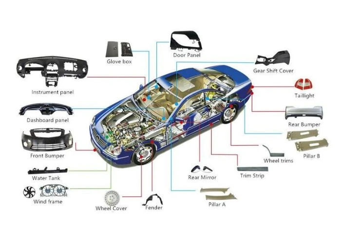
Plastic injection molds are commonly used to manufacture housings, connectors, automotive components, medical equipment parts, appliance components, and numerous consumer products. Their main advantage is the ability to reproduce complex geometries repeatedly once the tooling and molding process have been validated. However, this repeatability comes with a significant initial investment. Changes to wall thickness, parting lines, undercuts, or fastening features may require mold modifications after tooling is completed. For product development teams, understanding the mold’s capabilities and limitations early can reduce unnecessary engineering changes and improve the transition from prototype design to production.
How Do Plastic Injection Molds Work?
Injection molding follows a repeating cycle in which the mold and machine work together to transform plastic pellets into finished components. Although the basic sequence appears straightforward, each stage influences part quality, cycle time, and manufacturing stability. Engineers must understand how filling, packing, cooling, and ejection interact because a problem introduced during one stage may become visible only after the part is removed from the mold.
The cycle begins when the mold closes and the injection unit introduces molten plastic through the sprue, runner system, and gate into the cavity. The filling stage must deliver material throughout the intended geometry before excessive cooling restricts flow. Gate size, runner balance, melt temperature, injection speed, and part geometry all influence this process. Once the cavity is substantially filled, packing pressure helps compensate for material shrinkage as the plastic begins to cool. Insufficient packing can contribute to sink marks or internal voids, while excessive packing may create unwanted stresses or dimensional problems. These outcomes depend on the material and process conditions rather than a single universal setting.
During cooling, heat transfers from the molded plastic into the surrounding mold structure and its temperature-control system. Cooling time often represents a substantial portion of the molding cycle, particularly for thick sections or parts with uneven wall thickness. Once the component has cooled sufficiently to retain its shape, the mold opens and the ejection system releases the part. Ejector pin positions, draft angles, surface texture, and part geometry must be coordinated to avoid deformation or cosmetic damage. The mold then closes for the next cycle. Stable production requires the entire sequence to operate consistently, not merely that the cavity can be filled successfully once.
What Are the Main Types of Plastic Injection Molds?
Plastic injection molds can be classified by their structural layout, runner system, cavity count, and the mechanisms used to release complex parts. Different mold types are selected according to component geometry, production volume, material behavior, and automation requirements. Understanding these classifications helps engineers recognize why two molds producing similar-looking parts may have very different costs, maintenance requirements, and manufacturing capabilities.
Two-Plate vs Three-Plate Injection Molds
Two-plate molds are among the most common injection mold configurations. They typically have a single primary parting interface between the stationary and moving mold halves. Their relatively straightforward structure can make them suitable for many conventional plastic components, especially when gate placement and runner removal can be handled within a simple opening sequence. Two-plate molds are frequently used for housings, covers, brackets, and other parts that do not require a more complex separation mechanism. However, the optimal design still depends on the selected runner system, cavity arrangement, and the required gate location.
Three-plate molds introduce an additional plate separation, allowing the runner and molded part to be released through different opening movements. This arrangement can provide greater flexibility for certain gate locations, particularly with conventional cold-runner pinpoint gating. It may also allow automatic separation of the runner from the molded component in suitable designs. The additional mechanical structure, however, increases mold complexity and can affect tooling cost, opening stroke, and maintenance requirements. A three-plate mold should therefore be selected for a specific functional advantage rather than assumed to be a more advanced or universally better option.
Cold Runner vs Hot Runner Injection Molds
Cold runner molds use channels in which the plastic flowing toward the cavity generally cools and solidifies along with the molded part. Depending on the design, the runner may be separated and handled as additional material after each cycle. Cold runner systems can offer simpler tooling construction and may be practical for lower production volumes or materials that are difficult to manage in a hot runner. Their limitations can include additional runner material, handling requirements, and possible restrictions on gate placement or cycle efficiency. Whether runner material can be reused depends on the polymer, quality requirements, and production controls.
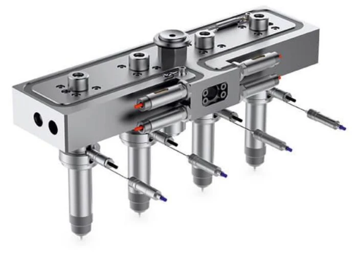
Hot runner molds use heated manifolds and nozzles to keep plastic molten within the distribution system between molding cycles. This can reduce or eliminate solidified runner waste and may improve efficiency in suitable high-volume applications. However, hot runner tooling requires additional components, temperature control, and maintenance expertise. It also introduces considerations related to material residence time, thermal degradation, color changes, and system cleaning. Engineers should compare the total production economics rather than evaluating the runner system only by its initial price. A higher tooling investment may be justified when the projected production volume and material savings support it.
Single-Cavity, Multi-Cavity, and Family Molds
A single-cavity mold produces one part per molding cycle and is often selected when production volume is limited, the component is relatively large, or tight process control is required. Multi-cavity molds produce several identical parts during each cycle, potentially increasing output without proportionally increasing cycle time. However, additional cavities require careful runner balance, cooling consistency, and dimensional control. If one cavity fills or cools differently from another, part-to-part variation can increase. Higher cavity counts also raise tooling complexity and may require a machine with greater clamping force or injection capacity.
Family molds produce different but related components within the same mold, such as several parts used in one product assembly. This can be attractive when the parts are required in matching quantities, but differences in part volume, wall thickness, and flow resistance may make balanced filling difficult. A family mold is therefore not automatically more economical than separate molds. The engineering team must consider production demand, quality requirements, and whether each component can be molded under compatible process conditions. In some projects, separate tooling provides better control and flexibility despite the additional initial investment.
Comparison Table: Common Types of Plastic Injection Molds
| Mold Type | Main Advantage | Main Limitation | Typical Application |
| Two-Plate | Simpler structure | Gate and runner layout constraints | General plastic parts |
| Three-Plate | Greater flexibility for certain gate layouts | More mechanical complexity | Pinpoint-gated parts |
| Cold Runner | Lower system complexity | Solidified runner material | Low- to medium-volume production |
| Hot Runner | Less runner waste in suitable applications | Higher tooling and maintenance cost | High-volume production |
| Multi-Cavity | Higher output per cycle | Filling and cooling balance | Repeated identical parts |
| Family Mold | Produces related parts together | Different parts may fill unevenly | Matched component sets |
The table shows that mold selection involves tradeoffs rather than a single hierarchy of quality. A simple two-plate mold may be the most efficient solution for a conventional component, while a hot runner or multi-cavity design may become economical at higher volumes. Complex part geometry can also require slides, lifters, or unscrewing mechanisms regardless of the basic mold classification. Engineers should therefore evaluate part design, expected production volume, process stability, and long-term maintenance together before selecting a tooling architecture.
What Materials Are Used to Make Plastic Injection Molds?
Plastic injection molds are commonly manufactured from tool steels, pre-hardened steels, stainless steels, and aluminum alloys. The appropriate tooling material depends on expected production volume, polymer characteristics, part geometry, surface finish, and maintenance requirements. Selecting mold material is different from selecting the plastic used to manufacture the product. Engineers must evaluate both separately because the mold must withstand repeated mechanical and thermal cycles while consistently reproducing the required part geometry.
Steel Injection Molds for Long-Term Production
Steel is widely used for production injection molds because suitable grades provide wear resistance, strength, and dimensional stability under repeated molding cycles. Pre-hardened steels such as P20 are commonly considered for general-purpose tooling, while hardened tool steels may be selected when greater wear resistance or longer production life is required. The choice also depends on cavity complexity, surface texture, molding pressure, and the presence of abrasive fillers in the plastic. For example, glass-fiber-reinforced polymers can accelerate wear in gates, runners, and cavity surfaces, making material selection and protective treatments especially important.
Steel tooling also offers options for polishing, texturing, repair, and replacement inserts, although these capabilities depend on the selected grade and mold construction. Higher hardness does not automatically mean a better mold. Harder steels can be more difficult to machine and modify, and certain grades may require additional heat treatment or specialized processing. Engineers should therefore balance wear resistance against manufacturing complexity and anticipated design changes. For a mature product with stable geometry and substantial production demand, a more durable steel mold may justify its initial investment. For an evolving design, flexibility and modification cost may deserve greater attention.
Aluminum Injection Molds for Prototype and Lower-Volume Production
Aluminum tooling is sometimes used for prototype injection molding and selected lower-volume applications because suitable aluminum alloys can be machined efficiently and provide useful thermal conductivity. These characteristics may reduce certain tooling manufacturing steps and support shorter development schedules when compared with more demanding steel-tooling designs. However, the actual advantage depends on part complexity, tolerances, required surface finish, and the mold manufacturer’s capabilities. Aluminum molds still require engineered cooling, gating, ejection, and alignment systems. They should not be confused with silicone molds used in vacuum casting, which operate through a different manufacturing process.
Aluminum is not universally suitable for every injection molding project. Highly abrasive polymers, demanding production volumes, or severe mechanical loading may favor steel tooling. Wear at gates, shutoff surfaces, and moving features must also be considered. Furthermore, the term prototype mold does not guarantee a particular mold life or accuracy level. Engineers should request documented expectations for production quantity, acceptable materials, maintenance, and dimensional capability. A well-designed aluminum mold can be valuable for specific development programs, but its suitability must be established from the actual application rather than from tooling material alone.
How Much Do Plastic Injection Molds Cost?
Plastic injection mold cost varies widely because every tooling project involves a different combination of geometry, material, cavity count, production volume, and engineering requirements. A relatively simple mold may cost substantially less than a multi-cavity tool containing complex moving mechanisms and advanced temperature-control systems. Rather than treating online price ranges as universal quotations, engineers should understand the main cost drivers and how they affect the total investment over the expected production life.
One major cost driver is part geometry. A component with straightforward external surfaces and a simple opening direction may require fewer mold components than a part containing deep undercuts, internal threads, side openings, or complex shutoff features. These structures can require slides, lifters, collapsible cores, or other specialized mechanisms. Such systems add engineering work, machining operations, assembly requirements, and maintenance considerations. Mold size also affects cost because larger tooling requires more material and potentially larger machining equipment. Even two plastic components with similar finished weights can demand very different molds if their geometries and ejection requirements differ substantially.
Cavity count and expected production volume create another important tradeoff. A multi-cavity mold generally requires more tooling investment than a comparable single-cavity design, but it may reduce the effective tooling cost per part over a sufficiently large production run. Hot runner systems can add initial expense while potentially reducing runner waste and downstream handling. Steel grade, surface texture, polishing, dimensional requirements, and mold qualification procedures also affect the quotation. For this reason, a meaningful comparison should identify what each supplier includes: design review, tooling fabrication, trial samples, modifications, spare components, and acceptance criteria.
Engineers should also distinguish tooling cost from the molded-part unit price. The total economics depend on the number of acceptable parts produced, molding cycle time, material consumption, scrap rate, and ongoing operating costs. A simplified way to evaluate the initial tooling burden is to divide tooling investment by the planned production quantity, but this calculation excludes many production expenses. If the product design changes after tooling approval, modification costs may further affect the project. Early design validation can therefore have financial value even when it does not directly reduce the mold manufacturer’s quoted price.
How Does Production Volume Affect Tooling Economics?
Consider an illustrative tooling investment of $20,000. If only 1,000 acceptable parts are produced, the initial tooling burden is $20 per part. If 20,000 acceptable parts are produced using the same tool, the corresponding burden falls to $1 per part. These figures are mathematical examples rather than current market quotations, and they exclude molding, material, shipping, maintenance, and other costs. The calculation demonstrates why production volume is central to tooling decisions. It also explains why engineers developing a small number of evaluation parts may choose a non-injection process before committing to a production mold.
What Design Factors Affect Injection Mold Quality?
Injection mold quality depends not only on how accurately the metal tooling is manufactured but also on whether the plastic part is designed for the molding process. Wall thickness, draft angles, undercuts, ribs, bosses, and gate placement all influence filling, cooling, ejection, and dimensional consistency. Engineers can reduce avoidable tooling complexity by addressing these considerations while the product geometry is still flexible, rather than waiting until the mold design has already been finalized.
Wall Thickness, Ribs, and Boss Design
Uniform wall thickness is a common design objective because abrupt thickness changes can create differences in cooling rate, shrinkage, and internal stress. Thick sections may develop sink marks or internal voids, while very thin regions can become difficult to fill. However, uniformity should be interpreted in relation to the material, flow length, and structural requirements rather than treated as an absolute rule. When a design requires thicker regions, gradual transitions and carefully designed reinforcement features can help manage the associated risks. Mold-flow analysis and supplier-specific design guidance may be necessary for complex geometries.
Ribs and bosses are frequently used to improve stiffness and provide mounting locations without making the entire part excessively thick. Their dimensions, placement, and connection to surrounding walls influence both structural performance and cosmetic quality. A thick rib base may create a visible sink mark on the opposite surface, while an inadequately supported boss may crack under fastening loads. The appropriate proportions depend on polymer type, wall thickness, and assembly requirements. Engineers should therefore evaluate these features as part of the complete component rather than applying one universal dimension to every material and product.
Draft Angles, Parting Lines, and Undercuts
Draft angles help molded components release from the cavity or core without excessive friction, deformation, or surface damage. The required draft depends on material shrinkage, surface texture, feature depth, and the direction of mold opening. Textured surfaces and deep walls may require more draft than shallow, polished features. A design that appears geometrically correct in CAD may still be difficult to eject if draft has not been considered. Engineers should also identify the parting line early because its position influences visible seams, flash risk, and how the mold separates around the product geometry.
Undercuts create another challenge because they prevent a component from being released through a simple straight opening motion. Side holes, external hooks, and certain internal features may require slides, lifters, or other moving mechanisms. These mechanisms can increase tooling cost, maintenance requirements, and the risk of mechanical wear. Sometimes a small geometry change can eliminate an undercut without compromising the product’s function. At other times, the feature is essential and must be accommodated through more complex tooling. The design decision should therefore balance product functionality, assembly requirements, appearance, and manufacturing consequences.
Gate Location, Cooling, and Dimensional Accuracy
Gate location determines where molten plastic enters the cavity and influences how the material flows around ribs, holes, and other geometric features. An unsuitable gate position may contribute to weld lines, air traps, uneven packing, or visible gate marks. Cooling design also affects dimensional quality because different regions of the part may shrink at different rates. Uneven cooling can contribute to warpage, especially in components with asymmetric geometry or substantial wall-thickness variation. These effects cannot be evaluated reliably from nominal CAD dimensions alone because material behavior and processing conditions are involved.
Dimensional accuracy should therefore be approached as a combined product-and-process requirement. Mold manufacturing accuracy is important, but it does not guarantee that every molded component will reproduce the cavity dimensions exactly. Polymer shrinkage, fiber orientation, packing conditions, cooling, and post-molding behavior can all affect the finished part. Engineers should identify critical interfaces, functional dimensions, and acceptable variation before tooling begins. This allows mold designers and molding specialists to prioritize the features that matter most instead of applying unnecessarily tight tolerances across the entire component.
What Are the Common Problems in Plastic Injection Molding?
Even a well-manufactured injection mold may produce defective parts when the material, geometry, and process conditions are not properly matched. Common defects include sink marks, warpage, short shots, weld lines, flash, and surface imperfections. Each defect can have several possible causes, so engineers should avoid assuming that a visible problem always originates from the mold itself. Effective troubleshooting requires examining part design, material behavior, tooling condition, and processing parameters together.
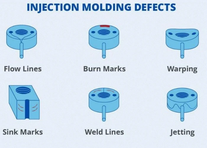
Sink marks are localized depressions commonly associated with thicker sections that cool and shrink differently from surrounding material. They may appear near ribs, bosses, or other concentrated masses. Warpage occurs when different regions of a component shrink or develop residual stress unevenly, causing the finished geometry to deviate from its intended shape. Although mold cooling and processing conditions influence both problems, product geometry can create the underlying risk. Reducing excessive thickness transitions and improving structural balance may therefore be necessary before process adjustments can provide consistent results.
Short shots occur when the cavity is not completely filled, leaving part of the intended geometry missing. Possible contributing factors include restricted flow, insufficient material delivery, premature cooling, or inadequate venting. Weld lines form where separate melt-flow fronts meet, and their appearance or mechanical significance depends on the material and local conditions. Flash is unwanted plastic that escapes through gaps between mold surfaces, potentially reflecting excessive pressure, inadequate clamping, wear, or poor mold fit. Each issue requires diagnosis rather than a single corrective action applied to every project.
An important distinction is that some defects can be anticipated during product design, while others become apparent only during molding trials. For example, prototype assembly can reveal interference between components, but a CNC-machined prototype will not reproduce weld lines created by molten plastic flow. Similarly, a machined part may help assess external geometry but cannot demonstrate the actual shrinkage behavior of a molded polymer. Engineers should use the appropriate validation method for each risk instead of expecting one prototype process to predict every production defect.
How Can Plastic Prototypes Help Before Injection Mold Tooling?
Plastic prototypes provide an opportunity to evaluate product geometry, assembly relationships, appearance, and selected functional characteristics before investing in production injection molds. They are especially useful while CAD designs are still changing and engineering teams need physical evidence to support design decisions. Different prototyping methods provide different information, so the objective should be to select the process that addresses the most important development risks rather than attempting to reproduce every characteristic of injection molding.
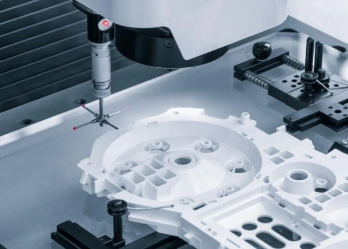
During early product development, plastic prototyping helps engineers evaluate physical designs and resolve selected geometry and assembly risks before production tooling is finalized.
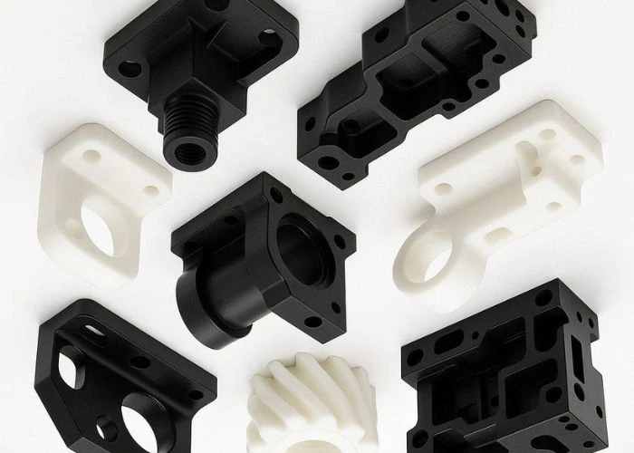
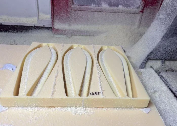
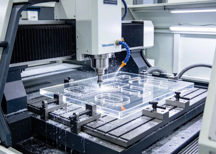
CNC plastic machining is useful when engineers need prototypes manufactured from specified engineering plastic stock. Depending on the material and geometry, CNC-machined components can support dimensional inspection, mechanical assembly evaluation, fastening checks, and selected material-related assessments. For example, a machined ABS housing may help verify whether internal supports align with the intended assembly and whether mounting interfaces are accessible. Engineers can then revise the CAD model before committing to expensive production tooling. However, machined stock and molded plastic may have different internal stresses, molecular orientation, and mechanical characteristics, so the results must be interpreted within the intended validation scope.
3D printing provides another development route, particularly when the main objective is to examine geometry quickly or compare several design alternatives. Printed models can help evaluate external form, internal clearances, accessibility, and assembly concepts before more representative material prototypes are required. However, printed polymers may differ substantially from injection-molded engineering plastics in strength, surface properties, and long-term behavior. Vacuum casting can support the production of multiple similar parts using silicone molds and suitable casting materials, making it useful for selected appearance and assembly studies. Neither process should be presented as an equivalent substitute for production injection molding.
For projects containing multiple plastic components, prototype assembly can reveal problems that are difficult to identify from isolated CAD models. These may include interference between housings, insufficient fastener access, misaligned locating features, and inconsistent visual gaps. Resolving these issues before production tooling can reduce the likelihood of later geometry changes. The value of this work comes from validating the product design rather than validating the injection molding process itself. Engineers should document which requirements have been confirmed through prototypes and which remain dependent on molding trials or production qualification.
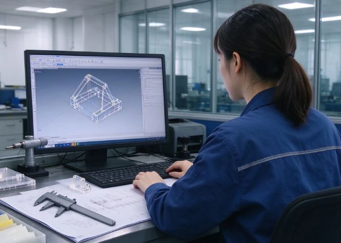
For products containing several mating components, complete prototype assembly services can help evaluate fit, alignment, and fastening accessibility before the design moves toward production.
When Should Engineers Choose CNC Machining or Vacuum Casting Before Tooling?
CNC machining, 3D printing, and vacuum casting can all support product development before production tooling, but they should not be selected using production volume alone. Engineers must also consider material requirements, dimensional accuracy, surface appearance, assembly complexity, and the purpose of the evaluation. Choosing a process that matches the current development question can reduce unnecessary iterations and prevent prototype results from being interpreted as evidence of performance they were never designed to demonstrate.
Selecting a suitable plastic prototype manufacturing process allows engineering teams to align material requirements, dimensional expectations, and development objectives with the capabilities of each method.
CNC machining is generally a strong candidate when the project requires specific engineering plastic grades, machined interfaces, or reliable dimensional inspection of critical features. It is often appropriate for functional geometry evaluation, fixture development, and assembly checks where the properties of the chosen stock material are relevant. For example, an industrial equipment housing may require accurate mounting positions and a material that behaves similarly to the intended design under selected mechanical loads. CNC machining can provide useful evidence for these requirements, provided the differences between machined and molded materials are recognized.
Vacuum casting becomes useful when the development team needs several similar parts for appearance reviews, assembly trials, or limited user-handling studies. A master pattern and silicone mold can reproduce suitable geometries without the investment required for production injection tooling. However, silicone molds have limited service life, and casting resins may not match the properties of the intended injection-molding polymer. Complex geometry, surface requirements, and part size can also influence feasibility. Vacuum casting should therefore be evaluated as a development and low-volume manufacturing method rather than as a direct replacement for every injection molding application.
For early-stage concepts, 3D printing may provide the fastest route to evaluating alternative shapes or internal arrangements, depending on the design and available process. As the project advances, CNC machining or vacuum casting may provide additional information about materials, appearance, or repeatability. A staged approach allows engineers to avoid committing to tooling before major geometry and assembly questions are resolved. Nevertheless, the final production design still requires appropriate molding-specific review. Successful prototype assembly does not establish that the same component can be molded economically or consistently at scale.
Comparison Table: Prototype Manufacturing Before Injection Mold Tooling
| Evaluation Requirement | CNC Machining | 3D Printing | Vacuum Casting |
| Engineering plastic stock | Strong option | Process-dependent | Casting resin rather than stock thermoplastic |
| Early geometry changes | Requires new machining | Often flexible | May require new master or mold |
| Critical machined features | Strong option | Depends on process | Requires evaluation |
| Multiple similar prototypes | Possible | Possible | Often suitable |
| Cosmetic appearance | Supports finishing | Process-dependent | Can reproduce suitable surface details |
| Injection molding process validation | Cannot replace | Cannot replace | Cannot replace |
The most useful approach is to match the prototype process to the engineering question being asked. A CNC prototype may be appropriate for checking precise interfaces, while a printed model may be sufficient for early design review. Vacuum casting can provide multiple representative parts for selected evaluation activities. None of these processes reproduces every aspect of production injection molding. Their value lies in reducing uncertainty before tooling investment, allowing the engineering team to make better-informed decisions about geometry, materials, assembly, and readiness for the next development stage.
Conclusion
Plastic injection molds play a central role in manufacturing plastic components consistently at scale. Their performance depends on mold structure, tooling materials, runner systems, cooling, and the design of the molded part. Understanding these factors helps engineers evaluate tooling costs, anticipate common defects, and select appropriate mold configurations.
Early design decisions involving wall thickness, draft, undercuts, and assembly features can significantly influence tooling complexity and production quality. Before investing in a production mold, plastic prototypes can help verify geometry, appearance, and assembly requirements. However, CNC machining, 3D printing, and vacuum casting cannot replace injection molding process validation. Each method should be used for the engineering questions it can reliably address.
FAQs
1. What Are Plastic Injection Molds Made Of?
Plastic injection molds are commonly made from pre-hardened steel, hardened tool steel, stainless steel, or aluminum alloys. The appropriate material depends on production volume, polymer characteristics, wear resistance, and surface requirements. Steel is frequently selected for long-term production, while aluminum may be suitable for certain prototype or lower-volume tooling applications.
2. How Much Does a Plastic Injection Mold Cost?
Injection mold cost varies substantially with mold size, cavity count, tooling material, part complexity, and production requirements. Simple tooling may cost much less than complex multi-cavity production molds. A reliable quotation requires the part drawing, material specification, expected production quantity, tolerance requirements, and information about any moving mold features.
3. What Is the Difference Between Two-Plate and Three-Plate Molds?
A two-plate mold generally uses a simpler opening arrangement with one primary parting interface. A three-plate mold adds another separation movement, which can provide more flexibility for certain gate and runner layouts. Three-plate designs may increase mechanical complexity and maintenance requirements, so the choice depends on the component and gating strategy.
4. How Long Do Plastic Injection Molds Last?
Mold life depends on tooling material, design, molding conditions, polymer abrasiveness, and maintenance. Some prototype molds are intended for relatively limited production, while durable production molds may be designed for hundreds of thousands or more cycles. No universal cycle count applies to every mold. Expected service life should be confirmed with the tooling supplier.
5. Can CNC Machining Replace Plastic Injection Molds?
CNC machining can manufacture plastic prototypes and selected production components without injection tooling. It is useful for engineering validation, small quantities, and applications requiring specific stock materials. However, it does not reproduce the complete injection molding process or necessarily provide the same economics at high production volumes. The methods serve different manufacturing requirements.
6. Why Should Engineers Build Prototypes Before Injection Mold Tooling?
Prototypes help engineers examine geometry, assembly fit, appearance, and selected material-related characteristics before committing to tooling. They can reveal design problems that would otherwise require costly changes later. However, prototype results should be interpreted carefully because non-injection processes cannot validate mold filling, production shrinkage, or other molding-specific behavior.