
A POM component can meet its drawing dimensions and still behave differently once it becomes part of a moving assembly. Clearance, contact conditions, alignment, machining variation, and accumulated tolerances all influence how a mechanism starts, runs, and changes after repeated use. For this reason, evaluating POM moving parts should focus on the complete motion relationship rather than relying only on material properties or individual dimensional inspection.
Motion Performance Depends on More Than POM Material Properties
POM is widely used in moving components, but selecting the material does not automatically produce a reliable mechanism. The actual motion depends on how the POM part interacts with surrounding components. Clearance, mating surfaces, contact pressure, and alignment all influence whether movement remains controlled or develops resistance, play, or uneven contact.
Clearance and Contact Conditions Shape Motion Quality
Clearance that is too small can increase resistance or cause local binding, while excessive clearance may create play, vibration, or poor positioning. At the same time, friction is determined by the complete contact pair rather than by POM alone. The mating material, surface condition, local geometry, and contact pressure all influence how smoothly the interface moves. This means a mechanism can use a suitable POM grade and still perform poorly if the mechanical relationship between the two surfaces is not appropriate. Evaluating operating clearance together with the actual contact condition gives engineers a more useful picture of motion quality than considering the material’s friction characteristics in isolation.
Alignment Errors Can Change the Entire Motion Relationship
Small alignment errors between shafts, guides, holes, or mating features can create uneven contact across a mechanism. One side may carry more load while another loses the intended clearance, producing resistance or irregular wear even when individual dimensions remain within tolerance. Misalignment can therefore be mistaken for a material or friction problem if the assembled geometry is not checked. For precision motion prototypes, engineers should evaluate whether the intended axes and guiding surfaces remain correctly related after assembly rather than assuming that accurate individual components automatically create an aligned mechanism.
What Should Engineers Evaluate During POM Motion Testing?
Static dimensional inspection confirms whether parts match the drawing, but motion testing shows how the mechanism actually behaves. A useful evaluation should observe both the immediate movement and the changes that develop after repeated operation, because these two stages can reveal different mechanical problems.
Resistance, Noise, and Mechanical Play Reveal Different Problems
The force required to start a mechanism may differ from its resistance during continuous movement. Tight spots can indicate insufficient clearance or alignment problems, while noise and vibration may point to uneven contact, backlash, or changing mechanical play. These symptoms should be considered together because they often originate from the same geometric relationship. Comparing motion across the full travel also helps determine whether a problem occurs at one position or throughout the mechanism. This provides more useful engineering evidence than simply judging whether the POM component feels smooth during a few manual movements.
Wear Patterns Show How the Mechanism Is Really Making Contact
Wear becomes more informative when engineers examine where it develops and how it changes with repeated cycles. Concentrated marks on one side of a guide, gear, or sliding surface may indicate uneven loading or misalignment, while increasing clearance can show that the original contact relationship is changing. The objective is not simply to determine whether wear exists, because some contact marks may be expected in a moving system. More importantly, engineers should determine whether the wear pattern remains controlled and whether it begins to change resistance, positioning, noise, or mechanical play.
Different Motion Systems Need Different Evaluation Priorities
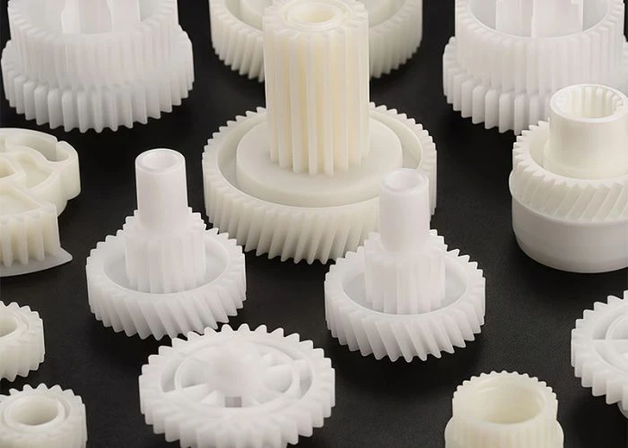
The same POM material can serve very different functions, so motion testing should reflect the mechanism rather than follow one generic checklist. Sliding and guiding interfaces require attention to running resistance, side play, alignment, and contact throughout the travel. Gear and rotational systems place greater emphasis on backlash, meshing consistency, rotational smoothness, and local wear. Positioning mechanisms should be evaluated for repeatability, return accuracy, and changes in mechanical play. Defining these priorities before testing helps engineers collect evidence that relates directly to the intended function instead of reducing the evaluation to a subjective judgement of whether the mechanism simply feels smooth.
CNC Accuracy and Assembly Tolerances Shape Final Motion
Moving mechanisms can make small dimensional variations more visible because several features interact at the same time. CNC plastic machining provides controlled geometry for POM parts, but individual machining accuracy is only one part of the final motion relationship. Engineers also need to consider how those dimensions combine after assembly.
Small Machining Errors Become More Visible in Motion
Hole positions, shaft diameters, guide spacing, mating surfaces, and reference features can all influence the path of movement. A small dimensional change that appears insignificant during individual inspection may alter clearance or contact once the component begins interacting with other parts. This is why machining accuracy matters particularly in mechanisms where several interfaces control the same movement. The value of accurate CNC machining is not simply that every POM component matches its drawing, but that controlled geometry reduces manufacturing variation when engineers are trying to understand the behaviour of the mechanism itself.
Tolerance Stack-Up Changes the Final Assembly Clearance
Several dimensions can individually remain within tolerance while their combined variation creates a mechanism that is tighter, looser, or less aligned than intended. A shaft, guide, mounting hole, and housing position may each be acceptable on their own, yet together they determine the final operating clearance. This is why checking individual parts cannot fully predict motion performance. Evaluating tolerance stack-up allows engineers to understand whether variation across several components is changing the mechanical relationship and helps avoid assigning a motion problem to one POM part when the real cause exists across the complete assembly.
Complete Assembly Reveals Problems Individual Parts Cannot
A POM component does not operate under the same conditions when tested individually and when installed in the complete mechanism. Fastening force, surrounding structures, support stiffness, and final alignment can all change where and how surfaces make contact. A slider that moves freely before assembly may develop resistance after screws are tightened, while a gear pair may show different backlash once its supporting components establish the final shaft positions. For prototypes intended to evaluate mechanism performance, motion testing should therefore be performed in the assembled state whenever possible. The goal is not only to confirm that every component fits, but also to determine whether the complete system preserves the intended clearance, contact relationship, and movement throughout its operating range.
When POM Is No Longer the Best Fit for the Mechanism
POM can be effective where controlled geometry and predictable movement are important, but the presence of motion alone does not make it the right choice. If the dominant load or operating environment changes, other material properties may become more important than the characteristics that originally made POM attractive.
Impact and Flexing Can Change the Material Priority
A mechanism exposed to repeated shock, sudden loading, or intentional flexing places different demands on the material than a controlled sliding or positioning system. Under these conditions, toughness or flexibility may become more important than maintaining rigid dimensional relationships. Engineers should therefore evaluate how the component is loaded during actual movement rather than selecting POM simply because it performs well in many precision mechanisms. When deformation is part of the intended function or impact dominates the load case, another engineering plastic may provide behaviour that is more representative of the final application.
Temperature and Chemical Exposure May Become the Limiting Factors
Motion performance is only one part of material suitability. If the mechanism operates at elevated temperatures or is exposed to chemicals, cleaners, fuels, or other aggressive media, environmental resistance may determine whether POM remains appropriate. A material that performs well during room-temperature motion testing may not represent the final application if its surrounding conditions are substantially different. Environmental requirements should therefore be considered together with mechanical movement so that the prototype does not validate one aspect of the mechanism while overlooking another condition that ultimately controls material selection.
Common Mistakes When Validating POM Moving Parts
Many motion problems are misdiagnosed because evaluation focuses on a single dimension, component, or material property. A more reliable approach is to examine how geometry, contact conditions, machining variation, assembly, and repeated movement interact inside the complete mechanism.
| Common Mistake | Better Engineering Approach |
| Checking dimensions without evaluating operating clearance | Evaluate clearance in the assembled mechanism |
| Assuming POM alone guarantees smooth movement 认 | Review contact conditions and alignment together |
| Testing only the first few movements | Compare behaviour before and after repeated cycles |
| Inspecting POM parts individually | Evaluate the complete motion system |
| Selecting POM only because the component moves | Match material choice to load, environment, and motion type |
Conclusion
Reliable POM motion depends on the complete mechanical relationship rather than on material properties alone. Clearance, contact conditions, alignment, machining accuracy, tolerance stack-up, assembly conditions, and repeated wear all influence how a mechanism behaves in use. Evaluating these factors as one system gives engineers a clearer view of real motion performance and makes it easier to identify whether a problem originates from geometry, manufacturing variation, assembly, contact conditions, or material selection.
FAQs
1. What Clearance Should Engineers Check in POM Moving Parts?
The correct clearance depends on the mechanism, load, mating surfaces, and operating conditions. Engineers should evaluate the final working gap after assembly because individual dimensions do not always represent the actual motion relationship.
2. Can a POM Part Be Dimensionally Correct but Still Move Poorly?
Yes. Alignment, contact conditions, assembly forces, and tolerance stack-up can affect movement even when every individual component meets its specified dimensions.
3. Why Should POM Mechanisms Be Tested Through Repeated Cycles?
Repeated operation can reveal wear patterns, changing resistance, increasing mechanical play, noise, or vibration that may not appear during initial movement.
4. How Does Tolerance Stack-Up Affect POM Motion?
Several acceptable dimensional variations can combine after assembly and change the final clearance, alignment, or contact relationship of the mechanism.
5. Does Low Friction Guarantee Smooth POM Movement?
No. Smooth motion also depends on clearance, mating surfaces, alignment, contact pressure, machining accuracy, and the geometry of the complete mechanism.
6. When Should Engineers Consider a Material Other Than POM?
Another material may be more suitable when impact, intentional flexing, temperature, or chemical exposure becomes more important than maintaining controlled dimensional relationships.