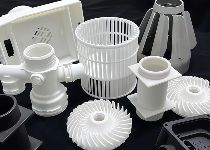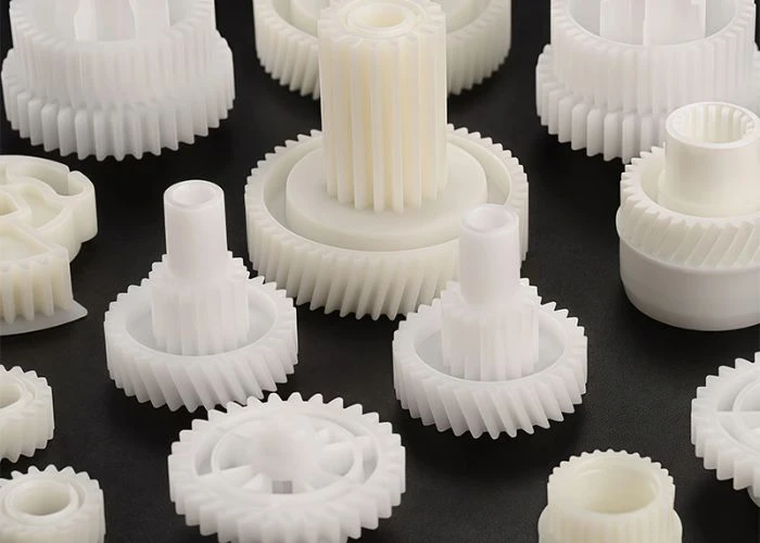

A Prototype Fit Check should do more than confirm whether parts can be assembled. In our plastic prototyping work, we use physical fit problems as evidence: where contact occurs, when alignment changes, and which interface controls the result. Before modifying a CNC-machined part, we first determine whether the real cause comes from geometry, location, finishing, fastening, assembly sequence, or the mating component.
A Prototype Fit Check Should Separate the Symptom From the Cause
When a prototype does not assemble as intended, the first visible problem is only a symptom. Tight fit, interference, uneven gaps, misalignment, or difficult fastener installation tells us where to begin looking, but it does not yet tell us which component or manufacturing step should be corrected.
In prototype manufacturing, it is tempting to modify the location where interference is easiest to see. If a housing edge contacts another component, sanding that edge may immediately allow the parts to assemble. However, the contact could actually be caused by an incorrectly located boss somewhere else.
The same applies to a panel with an uneven gap. The panel itself may be accurate, while an internal bracket prevents it from fully seating. Correcting the visible panel would then compensate for another problem rather than solve it.
For this reason, I treat the first visible fit problem as diagnostic evidence rather than as the root cause. A tight fit may result from direct interference, incomplete seating, or a locating feature that shifts one component toward another. An uneven gap may originate from an internal bracket or fastening condition rather than from the visible panel itself. Similarly, a misaligned hole may reflect the combined position of several components instead of an error in the hole alone.
The symptom tells us where to begin the Prototype Fit Check, but it should not determine the correction. I first trace the physical relationship that produces the problem and confirm which feature actually controls it. Only then can we decide whether a part needs machining correction, assembly adjustment, or no modification at all.
Start the Prototype Fit Check at the Exact Problem Interface
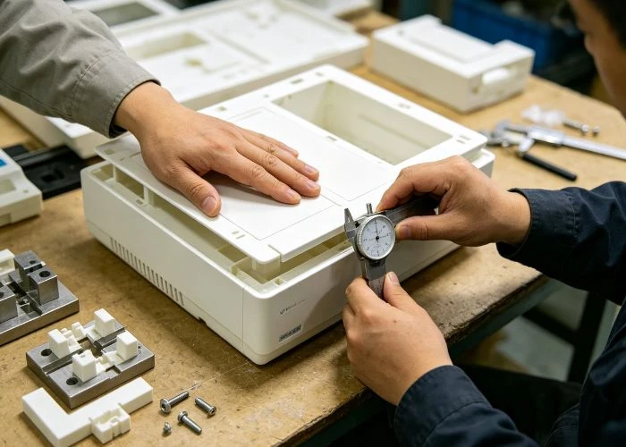
A complex prototype may contain dozens of parts, but most fit problems become visible at a much smaller physical interface. I therefore narrow the problem before measuring the entire assembly. The goal is to identify the two features that first contact, fail to align, or prevent the next assembly step.
Suppose a plastic housing cannot close completely. “The housing does not fit” is too broad to guide a correction. I want to know whether the first unwanted contact occurs at a locating boss, internal rib, bracket, connector, cable, screw head, mating edge, or another feature.
Physical evidence is useful here. Contact marks, scratches, compressed paint, witness marks, partial seating, or a changing gap can show where two components are interacting.
For complicated assemblies, we may remove one non-controlling component at a time and repeat the fit check. If removing one bracket allows the housing to seat correctly, the investigation becomes much more focused.
This is more reliable than immediately measuring every dimension on every part.
Check Whether the Parts Are Fully Seated Before Measuring the Gap
An uneven gap does not automatically mean the visible edges were manufactured incorrectly. One side of the assembly may simply not be fully seated.
Before measuring the gap, I check the intended contact surfaces. A small burr, trapped cable, paint buildup, unfinished edge, misplaced insert, or internal component can hold two parts apart. Tightening the screws may hide the resistance without eliminating its cause.
This distinction matters because measuring a gap while a component is partially seated produces a real measurement of the wrong assembly condition.
I therefore verify the seating condition first and the resulting gap second. If the part sits correctly only after force is applied, that is also useful diagnostic information—the assembly may be compensating for an interference rather than fitting naturally.
Compare the Physical Fit With the Current CAD Assembly
Once the physical interface is isolated, I compare what we see on the bench with what the current CAD assembly says should happen. This prevents us from correcting a manufactured part to compensate for outdated files, incorrect orientation, or a component revision that no longer matches the assembly.
Revision control is especially important during rapid product development. A housing may be manufactured from Rev C while a bracket, purchased component, or assembly file still represents Rev B.
Both physical parts can be manufactured correctly according to their individual files and still be incompatible with each other.
Before treating the problem as a manufacturing error, I confirm that the physical assembly matches the current design intent. This means checking whether all components belong to the same revision, whether they are installed in the correct orientation, and whether the contact or clearance seen on the bench agrees with the CAD assembly. I also compare critical purchased or customer-supplied components with the models used during design.
This review is important because a revision mismatch can look exactly like a machining problem. If a Rev C housing is assembled with a Rev B bracket, modifying either component to make that combination fit may create a new problem when the correct revision is used. A Prototype Fit Check should therefore verify the design baseline before any physical correction begins.
Determine Whether the Fit Problem Comes From One Part or the Assembly Relationship
After confirming the correct CAD and assembly condition, I inspect the features that actually control the problematic interface. At this stage, dimensional inspection becomes useful because we now know which measurements can explain the fit problem instead of measuring unrelated geometry.
The simplest case is a controlling feature that is outside its specified tolerance. If an incorrectly sized boss directly causes interference with a mating hole, the relationship between cause and correction is relatively clear.
Even when Part A and Part B both pass dimensional inspection, the final assembly can still fail if the locating relationship or accumulated dimensional variation moves the components in an unfavorable direction.
That does not automatically mean the inspection was wrong. Several allowed dimensional variations may combine in the same direction, or the assembly may be located by features different from those initially assumed.
This is where part inspection and assembly diagnosis must work together.
Research on dimensional management similarly treats assembly fit as a result influenced by datums, assembly sequence, assembly method, part tolerances, and variation contributors rather than assuming the visible problem identifies its own cause.
When Both Parts Pass Inspection, Check the Assembly Relationship
If individual components meet their drawing requirements, I trace how they locate each other physically. A boss, shoulder, mounting face, pin, screw clearance, or intermediate bracket may shift the final relationship even though each isolated measurement is acceptable.
At this point, I avoid solving the problem by arbitrarily tightening every dimension. The more useful question is which dimensional relationship can actually move the failed fit condition.
Our separate guide to prototype assembly tolerance explains how engineers can define fit, gap, alignment, clearance, and other assembly-level requirements before manufacturing. Here, during the fit check, those requirements become diagnostic references rather than theoretical values.
Check Whether Fastening Creates the Assembly Fit Problem
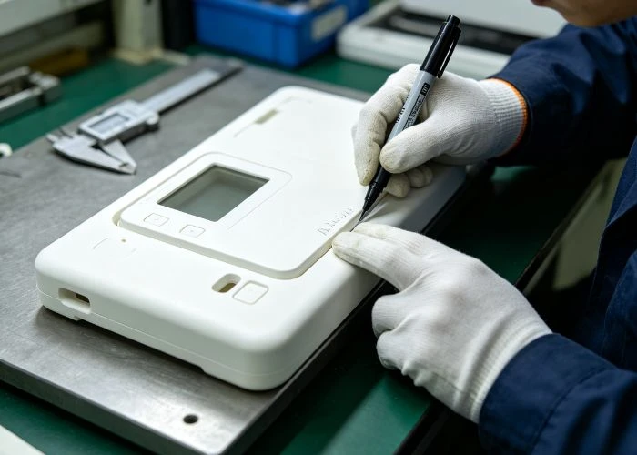
Some prototypes fit correctly when components are placed together loosely but move out of position as fasteners are tightened. This is a valuable clue. It tells me the problem may not be the free-state geometry alone; the fastening process is changing the physical relationship.
I compare the assembly at several stages: first with the parts positioned freely, then with the fasteners inserted but still loose, and finally during partial and full tightening. If the gap or alignment changes at one particular stage, that change gives us a useful clue about whether fastening is influencing the fit.
If the gap or alignment changes at one specific stage, we have narrowed the problem significantly.
For example, a screw passing through a clearance hole can pull a panel sideways if the design lacks a stronger locating feature. Another assembly may distort because the screw clamps two surfaces that were not fully seated.
The tightening sequence can also expose the problem. If tightening one corner first creates a gap on the opposite side, I want to understand why before changing the visible edge.
Do Not Use Fasteners to Hide an Interference Problem
A screw can sometimes pull two plastic parts together even when they do not naturally seat. The final assembly may look closed, but the fastener is storing load in the components.
For a prototype fit diagnosis, I do not consider this automatically acceptable. The important question is whether the preload is intentional or whether the screw is forcing the assembly to overcome an unintended interference.
This is particularly relevant to plastic parts because local flexibility can make a forced assembly appear successful. After the screws are released, the parts may spring apart again, revealing that the underlying mating condition was never correct.
Check the Actual Mating Component Before Modifying the Prototype
Plastic prototypes frequently mate with components that were not manufactured in the same process: displays, PCBs, switches, motors, connectors, lenses, bearings, inserts, fasteners, or customer-supplied hardware. When one of these interfaces fails, I verify the actual counterpart before modifying the prototype.
A simplified CAD model may represent the nominal envelope of a purchased component but omit a seam, cable exit, connector latch, edge radius, or other local geometry.
The physical component may also be a different revision or supplier variant from the model used during design.
If a connector does not fit through a CNC-machined opening, enlarging the opening immediately could be the wrong correction. First, I compare the actual connector with the CAD reference and confirm which geometry creates the interference.
Our complete prototype services article explains the broader workflow for integrating customer-supplied components during prototype build and trial assembly.
Ask Whether the Fit Problem Appeared Before or After Surface Finishing
When a prototype includes painting, polishing, sanding, silk screening, or other finishing work, the timing of the fit problem can help isolate its cause. I compare the pre-finish and post-finish condition rather than assuming that every final assembly issue originated during CNC plastic machining.
If the parts fitted correctly before painting but become tight afterward, the investigation should focus on interfaces affected by coating, masking boundaries, edge buildup, or post-machining preparation.
If the problem already existed before finishing, paint is unlikely to be the original cause.
Polishing creates a different diagnostic condition because it removes material. Excessive manual refinement near a visible mating edge can alter a gap even when the original CNC geometry was correct.
This before-and-after comparison helps us avoid correcting the machining process for a variation introduced later.
Reproduce the Fit Problem Before Making a Correction
Before making any physical correction, I try to reproduce the fit problem under the same assembly conditions. A repeatable interference, gap, or alignment issue gives us stronger evidence that the problem is controlled by a specific physical relationship rather than by handling or a one-time assembly variation.
During repeated checks, I observe whether the condition changes with the assembly sequence, fastening method, or component position. If the same gap returns after the parts are disassembled and rebuilt, the problem is more likely to come from a consistent geometric or locating relationship. When equivalent components are available, comparing them can also help determine whether the issue follows one specific part or remains with the assembly.
Photos, measurements, and contact marks can preserve the original condition before any material is removed. The purpose is not to create a complex inspection report, but to collect enough evidence to identify the controlling cause. This makes the Prototype Fit Check a diagnostic process rather than a simple pass-or-fail assembly test.
Correct the Controlling Cause, Not the Easiest Part to Modify
Once the evidence points to a controlling cause, the correction should target that relationship as directly as possible. This is where a disciplined Prototype Fit Check prevents unnecessary rework: we know why a change is being made and what result it is expected to improve.
Imagine a cover with an uneven gap caused by an internal bracket sitting too high. Sanding the visible cover edge might make the gap look better, but the correction would be compensating for the bracket rather than fixing the relationship.
The correct action could instead involve the bracket location, its seating surface, a locating boss, or another controlling feature.
Likewise, if the problem comes from an outdated mating component, modifying a correctly machined plastic part may create a new problem when the correct component arrives.
This principle is particularly important in CNC plastic machining because local corrections can be physically easy. Easy modification should never be confused with correct modification.
Recheck the Original Problem and Look for New Side Effects
A correction is not complete simply because the original parts now assemble. I repeat the same fit condition and verify that the original symptom has been removed without creating another problem elsewhere.
Changing one locating feature may improve a panel gap but shift a connector opening. Enlarging one clearance may remove interference but increase movement. Adjusting a bracket may correct display alignment while changing button position.
For this reason, I compare the revised assembly with the original acceptance requirement rather than judging the correction only by whether installation became easier.
Dimensional Inspection and Prototype Fit Check Should Support Each Other
Dimensional inspection and physical fit checking answer different questions. I use inspection to verify the geometry identified during diagnosis, while the fit check confirms whether the real components create the intended relationship. Neither method should be expected to replace the other.
A dimension can pass inspection while the assembly still fails because several relationships combine. Conversely, a prototype can sometimes be forced to assemble even though an important feature is outside its drawing requirement.
External prototype-validation guidance makes a similar distinction: dimensional inspection verifies critical geometry, while assembly testing evaluates fit, clearance, fastener engagement, and relationships between real components.
For individual critical dimensions, our guide to plastic manufacturing tolerances explains how engineers can define feature relationships, datums, and inspection requirements. During a fit diagnosis, I use that information selectively on the features connected to the observed problem.
How We Diagnose a Prototype Fit Problem at UForProto
At UForProto, we are a direct plastic prototype manufacturer rather than a trading company. When a project includes mating prototype parts, our goal is not simply to make the components assemble. We use CAD data, drawings, physical parts, and actual assembly conditions to identify what controls the fit problem before deciding whether any part should be modified.
Prototype Fit Check Diagnosis Process
| Step | Prototype Fit Check | What We Verify |
| 1 | Identify the Fit Problem | Record where interference, tight fit, uneven gap, or misalignment appears and under what assembly condition. |
| 2 | Isolate the Problem Interface | Identify the specific mating surfaces or features directly involved instead of inspecting the entire assembly without a clear target. |
| 3 | Confirm Part Seating | Check whether mating surfaces are fully seated and whether burrs, cables, inserts, paint, or internal components are preventing correct contact. |
| 4 | Compare With CAD | Confirm CAD revision, component orientation, nominal clearance, intended contact, and whether all physical parts belong to the same design revision. |
| 5 | Inspect Critical Features | Measure only the dimensions and locating features that can realistically influence the observed fit problem. |
| 6 | Review Locating and Fastening | Check whether the assembly position changes when screws or other fasteners are inserted and tightened. |
| 7 | Verify Mating Components | Compare displays, connectors, PCBs, fasteners, or other supplied components with the geometry used in the CAD assembly. |
| 8 | Reproduce the Problem | Repeat the assembly under the same conditions to confirm that the problem is consistent rather than caused by handling or an isolated assembly event. |
| 9 | Correct the Root Cause | Modify the feature or relationship supported by the inspection and fit-check evidence instead of simply modifying the easiest accessible part. |
| 10 | Reassemble and Verify | Repeat the fit check to confirm that the original problem is resolved without creating a new gap, alignment, clearance, or assembly issue. |
This process keeps the Prototype Fit Check focused on root-cause diagnosis rather than trial-and-error modification. In our plastic prototyping and CNC plastic machining projects, the sequence may vary with the assembly, but the principle remains the same: we confirm the physical relationship first, identify the controlling cause, and only then decide what should be corrected.
What Engineers Should Provide for a Useful Prototype Fit Check
A useful Prototype Fit Check depends on understanding what the assembly was originally intended to achieve. For a multi-part plastic prototyping project, I recommend providing the current 3D CAD assembly, individual part files, critical 2D drawings, and any defined requirements for fit, clearance, alignment, or fastening.
Revision information is especially important when the design changes during prototype manufacturing. If a housing, bracket, or supplied component comes from a different design revision, the resulting fit problem may not be caused by CNC plastic machining at all. Confirming which files and physical components belong together helps us avoid diagnosing a revision mismatch as a manufacturing error.
If a fit problem has already appeared, engineers should also explain where it occurs and under what condition it becomes visible. Knowing whether the problem is repeatable, whether it existed before surface finishing, or whether it changes as fasteners are tightened can significantly narrow the investigation. Photos and measurements of the actual failed condition are also useful because they allow us to compare the physical assembly with the CAD relationship before any part is modified.
Information about mating components is equally important. If the prototype interfaces with a display, PCB, connector, switch, fastener, or another customer-supplied component, I prefer to review the actual component data whenever the interface is critical. This gives us a clearer basis for determining whether the problem comes from the manufactured prototype, the mating component, or the relationship between them.
Conclusion
A Prototype Fit Check is most valuable when it explains why an assembly problem occurs, not simply whether parts fit. By isolating the problem interface, confirming seating, checking CAD revisions, measuring controlling features, reviewing fastening and finishing effects, and verifying actual mating components, engineers can correct the true cause instead of modifying the easiest part. This approach makes physical prototypes more useful for design decisions and reduces unnecessary rework between development rounds. For a multi-part plastic prototyping project, send UForProto your CAD assembly, drawings, mating-component information, and fit requirements for engineering review and a quotation.
FAQs
1. What Is a Prototype Fit Check?
A Prototype Fit Check is a physical review of how prototype components mate, locate, clear, and assemble with each other or with actual supplied components. A useful fit check evaluates more than whether installation is possible; it helps determine whether the intended physical relationship has been achieved.
2. Why Can Two In-Tolerance Prototype Parts Still Have a Fit Problem?
Individual parts can meet their drawings while their allowed dimensional variations combine unfavorably in the assembly. The final relationship can also depend on locating features, intermediate components, fastening, finishing, and actual mating hardware rather than one dimension alone.
3. Should I Modify a Prototype as Soon as I Find Interference?
Usually, I first identify the controlling cause. Removing material at the visible contact point can make one assembly fit while hiding a dimensional, locating, revision, or mating-component problem elsewhere. The physical evidence should be recorded before modification whenever practical.
4. Can Surface Finishing Cause a Prototype Fit Problem?
Yes. Painting can add material at mating areas, while sanding or polishing can remove material near controlled edges. Comparing the fit before and after finishing helps determine whether the problem originated in CNC plastic machining or was introduced during a later process.
5. What Is the Difference Between Dimensional Inspection and a Prototype Fit Check?
Dimensional inspection verifies specified geometry against drawings or requirements. A Prototype Fit Check verifies the physical relationship created when real components come together. Both are useful: inspection helps identify dimensional causes, while fit checking reveals assembly behavior that isolated measurements may not show.
6. What Should I Send to UForProto for a Prototype Fit Check?
Send the current 3D CAD assembly, individual part files, critical 2D drawings, fit or assembly requirements, and data for mating components. If a problem already exists, include photos, measurements, revision information, and details about when the issue occurs.