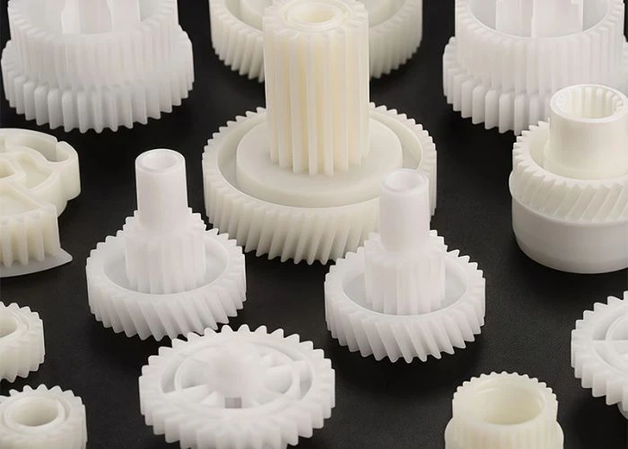

CNC machining plastic without warping or cracking is not achieved by changing one cutting parameter. In our workshop, we often find that a plastic part remains stable while it is clamped but changes after heavy material removal, repositioning, or fixture release. Reliable CNC plastic machining therefore requires us to manage the part’s condition throughout the process—not simply machine the CAD geometry accurately.
Why Plastic Can Warp or Crack Even When CNC Machining Is Accurate
Accurate tool movement does not guarantee that a plastic part will remain in the same condition after machining. During CNC plastic machining, material removal changes the stiffness of the workpiece, clamping introduces temporary constraint, and cutting heat can produce local dimensional movement. A stable result therefore depends on controlling how the part changes between machining stages.
When we identify a part with a large cavity, substantial one-sided material removal, long unsupported areas, or several critical interfaces, we do not normally treat every operation as one continuous path to final dimensions. Before machining, we review where stiffness will decrease as stock is removed and which dimensions will still matter after the part is released from the fixture.
For higher-risk geometry, we may first establish stable reference surfaces and remove the majority of non-critical stock while leaving controlled allowance around important faces, openings, or mating features. After this major change in section, the semi-finished part can be released and its condition checked before we decide how the final setup should reference it.
If movement has occurred, the solution is not simply to force the part back into its original position with stronger clamps. We determine whether sufficient allowance remains to re-establish the required datum and finish the critical geometry from the new condition. If movement is excessive, the roughing sequence, workholding, or stress-relief plan needs to be corrected before continuing.
This is an important distinction in CNC machining plastic without warping or cracking: we do not try to prevent the material from responding to machining at all. We plan the process so that the major response occurs before the dimensions that matter most receive their final cut.
Material Removal Strategy Should Control When the Part Becomes Flexible
For a high-removal plastic part, the machining sequence determines not only efficiency but also when the workpiece loses the stiffness provided by the original stock. In our workshop, we therefore consider which material should remain temporarily to support later operations instead of removing every accessible area as early as possible.
We Rough the Part According to the Geometry That Will Remain
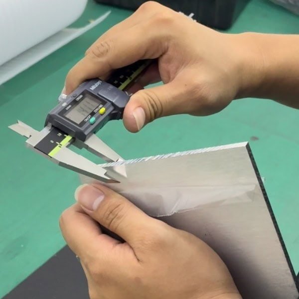
For a deep housing machined from solid stock, removing the entire internal cavity first may leave the outer walls and mounting regions with much less support for subsequent operations. Instead, we can divide the roughing operation so that the part retains useful rigidity while the main cavity and external geometry are established.
Where both sides require substantial machining, the sequence can also be arranged to avoid completing all heavy removal from one side while the opposite side remains close to the original blank condition. The exact approach depends on geometry, but the principle is consistent: we try to avoid creating a severely unbalanced semi-finished part earlier than necessary.
We also retain machining allowance deliberately rather than uniformly. A cosmetic surface with generous finishing stock does not need the same allowance strategy as a mating face, controlled opening, or datum that may need to be re-established after roughing. The allowance should remain where it gives us useful correction capability later.
We Re-Establish Critical Geometry After the Major Material Removal
Once roughing has removed the material most likely to change the part’s condition, we can release the workpiece and evaluate what actually happened. If the part remains stable, finishing can continue as planned. If it has moved within a manageable range, we can establish the next setup from the semi-finished condition rather than reproducing the original clamped geometry.
This is where a staged process becomes useful. The final machining of critical holes, mating faces, controlled openings, and other assembly-related features can be performed after the largest structural change has already occurred.
For us, roughing and finishing are therefore not separated simply because “plastic needs two machining stages.” They are separated when doing so gives us a useful point to release, observe, re-reference, and correct the part before committing the final dimensions.
Clamping Must Hold the Part Without Manufacturing a False Geometry
Increasing clamp pressure can make a plastic workpiece appear more stable during machining, but that does not necessarily improve the finished part. Our workholding strategy is based on where cutting forces enter the part, how the workpiece is supported, and whether the fixture is changing the geometry that we later intend to measure.
If a slightly bowed plastic blank is pulled tightly against a flat fixture, the CNC machine can produce highly repeatable dimensions while the clamps remain engaged. Those dimensions, however, are being generated on a temporarily flattened workpiece. Once the fixture is released, the original force disappears and the machined relationships may change.
When we see this risk, we first review the support condition rather than simply increasing clamp force. Contact should be placed where it can resist the expected cutting load without unnecessarily forcing flexible areas into position. Clamp forces should also be distributed so that one local contact does not become the dominant source of deformation.
After heavy roughing, we reassess the setup because the same fixture may behave differently once most of the original stock has disappeared. A clamping arrangement that was appropriate for a rigid blank can over-constrain a lighter semi-finished housing.
For critical parts, we also compare the released condition with the clamped condition before final machining. If a datum or mating face changes significantly after release, we know that continuing to reference the old fixture condition would reproduce the wrong geometry. At that point, the setup must be corrected before the final dimensions are cut.
Heat Must Be Removed Without Creating a New Machining Problem
Heat control in CNC plastic machining is not solved by simply reducing spindle speed or feed. Our objective is to keep the cutter producing a clean chip, remove that chip efficiently, and prevent unnecessary rubbing or prolonged heat concentration around critical geometry.
When we see chip softening, poor evacuation, surface smearing, or increasing tool rubbing, we treat these as process signals rather than waiting for visible melting. Depending on the feature, we may adjust cutter engagement, feed, spindle condition, toolpath, or chip-clearing method so that the cutting edge removes material instead of repeatedly working the same hot surface.
Deep cavities require particular attention because chips and heat are harder to remove from the cutting zone. In these areas, we may avoid continuous heavy engagement, improve evacuation, and divide the toolpath so that the cutter does not spend excessive time concentrating heat in one local region.
We also avoid solving thermal problems by simply making every cut extremely light and slow. If chip formation becomes inefficient, the tool can rub instead of cut and increase heat input. The correct adjustment therefore comes from observing chip formation, tool engagement, surface condition, and part temperature together.
For critical dimensions, we do not rely on measurements taken immediately after a heat-generating operation when thermal movement could be meaningful. The part should return to a representative condition before the geometry is accepted or used as the basis for another critical operation.
Crack Prevention Starts Before the Cutter Reaches the Weakest Feature
Cracks rarely appear because of one isolated tool movement. By the time a cutter reaches a hole near an edge, a narrow bridge, or a sharp internal transition, earlier material removal may already have reduced the support around that feature. We therefore control cracking through the sequence leading into the feature, not only through the final cut itself.
For a vulnerable feature, we first consider whether surrounding stock should remain temporarily while the nearby geometry is machined. Keeping useful support longer can reduce local movement and prevent the feature from receiving full cutting load when it is already at its weakest condition.
We then control how the cutter enters and leaves the region. Sudden engagement, excessive local cutting load, poor chip clearance, or repeated heat concentration can all increase stress around an already sensitive feature. Adjusting the toolpath and distributing material removal over several controlled operations can be more effective than simply reducing one machine parameter.
If the material itself shows signs of significant residual stress, continuing to machine progressively smaller features may not be the correct response. We can stop before the final feature is committed, evaluate the semi-finished condition, and determine whether stress relief or a revised setup is required.
The important manufacturing habit is to protect the weak feature before it becomes weak. Once a crack has formed, polishing or finishing cannot restore the original structural continuity of the prototype.
Stress Relief Is a Process Decision, Not a Default Step for Every Plastic Part
Annealing and other stress-relief approaches appear frequently in discussions of plastic machining because they can reduce residual stress in appropriate applications. However, treating annealing as a universal requirement oversimplifies CNC plastic machining. We consider it only when the expected stability benefit justifies adding it to the manufacturing route.
For many straightforward prototype parts, good stock, appropriate workholding, controlled cutting, and a sensible machining sequence are sufficient. Adding thermal processing automatically would increase lead time without necessarily improving the result.
The decision becomes more relevant when the blank condition, amount of material removal, geometry, previous machining response, or dimensional requirement indicates that residual stress is likely to remain a significant part of the problem. In some cases, stress relief before machining may be appropriate; in others, the more useful point is after roughing, when the largest change in section has already occurred.Industry guidance on plastic annealing also distinguishes between routine machining and applications where stress-relief steps are justified by dimensional-stability risk.
We do not apply one annealing temperature or cycle across engineering plastics, and this article is not intended to turn thermal treatment into a material-selection guide. The manufacturing principle is simpler: stress relief is useful when it creates a more stable condition for the machining that still has to follow.
Final Inspection Tells Us Whether the Process Actually Worked
For deformation-sensitive parts, inspection is not only a pass/fail check at the end of machining. We use it to confirm whether the workholding, material-removal sequence, thermal control, and finishing strategy have produced geometry that remains meaningful after the temporary machining conditions are removed.
After the relevant machining operations are complete, the part is released from unnecessary fixture constraint and allowed to return to a representative temperature condition. We then focus inspection on the features most likely to reveal process instability: flatness, mating faces, controlled openings, hole relationships, datum surfaces, and geometry that affects later assembly.
If these features remain within the required condition after release, the machining strategy has controlled the part rather than merely controlling the machine. If they change beyond the acceptable range, we use the direction and location of that change to trace the likely source—workholding, material removal, thermal influence, or residual stress—before deciding whether rework is technically appropriate.
That feedback is valuable for repeat parts as well. Once we understand where a particular geometry is sensitive, the next part can be manufactured with the corrected roughing sequence, fixture condition, or finishing approach from the beginning instead of repeating the same instability.
How We Control High-Risk Plastic Parts During Prototype Machining
For us, deformation control is not a separate corrective operation performed after machining fails. It begins when we review how much stock will disappear, which features need to remain stable after release, and how the part will change between setups. That information determines the manufacturing route before the first critical surface is finished.
As a direct plastic prototype manufacturer, our focus is on converting an existing engineering design into a stable physical part. We are not trying to replace the customer’s material specification or redesign the product around easier machining. Instead, we identify where the specified material and geometry create manufacturing risk and decide how the machining process should respond.
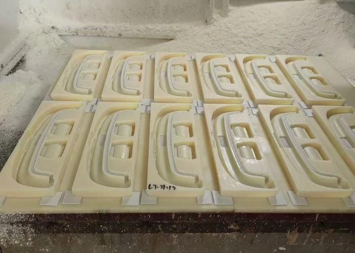
For a higher-risk part, that can mean controlling the first roughing operation, retaining useful finishing allowance, changing the datum after the workpiece has relaxed, revising workholding as stiffness changes, and delaying critical finishing until the part is in a condition that better represents its final state. Heat and local cracking risk are considered within the same sequence rather than as separate problems.
This is particularly important in plastic prototyping, where the part may later be used for assembly, appearance evaluation, or engineering review. A prototype that only matches CAD while it is held in the machine does not provide the engineering team with reliable physical information.
Thin-Wall Plastic Parts Need a Different Level of Deformation Control
Thin walls introduce an additional problem beyond the stress mechanisms discussed above: the remaining structure may become flexible enough to move under the cutting force itself. At that point, the cutter may be machining a temporarily displaced wall rather than a rigid surface, creating a different dimensional-control problem.
We deliberately do not treat that as simply another example of residual-stress warping. Thin-wall CNC plastic machining requires deeper consideration of wall support, cutting-force direction, temporary deflection, spring-back, and the sequence in which the final wall thickness is created.
Those issues deserve a separate machining strategy. We cover wall support, cutting-force direction, temporary deflection, spring-back, and machining sequence in our dedicated guide to CNC machining thin plastic parts.
What Information Matters When Warping or Cracking Is a Project Risk?
For deformation-sensitive work, more specifications do not automatically create a better machining plan. What helps us most is knowing which geometry must remain correct after the part is released and which relationships actually determine whether the prototype can perform its intended engineering evaluation.
If flatness controls an assembly interface, we need to know that. If a large opening must align with another component, that relationship matters more than applying the same tight tolerance to every non-critical surface. If a particular face becomes the datum for later assembly, its stability deserves more manufacturing attention than an isolated cosmetic dimension.
The same applies to material information. If the grade and stock requirement are already fixed, they should be supplied clearly so we can plan around them. If they are not fixed, that is a separate engineering discussion; it should not turn a warping-control project into another generic material-selection exercise.
When material selection is still open, our guide to dimensionally stable plastics explains how material behavior, moisture, temperature, and machining conditions can affect dimensional accuracy.
For quotation and manufacturing review, CAD data together with critical tolerances, mating relationships, quantity, and the intended prototype use usually tells us much more than a blanket request for “maximum accuracy.”
Conclusion
CNC machining plastic without warping or cracking depends on controlling the part throughout machining, not only on cutting accuracy. Material removal, clamping, heat, and stress release can all change the part after machining. A more reliable process is to identify high-risk areas early, separate roughing and finishing when needed, and verify critical geometry after the part is released. If you have a deformation-sensitive plastic prototype, you can send us your CAD files and project requirements for manufacturing review and quotation.
FAQs
1. Why Does Plastic Warp After CNC Machining?
Plastic can warp when material removal changes the stress balance and stiffness of the original stock. The part may remain constrained by the fixture during machining, so the movement becomes visible only after unclamping or repositioning. Heat and asymmetric material removal can increase the effect.
2. Can a Plastic Part Be Within Tolerance on the Machine but Out of Tolerance After Release?
Yes. Fixture pressure can temporarily hold a plastic part in a geometry different from its free state. If critical dimensions are finished under that constraint, they may change after release. This is why deformation-sensitive parts should also be evaluated in a condition representative of their final use.
3. Does Every Plastic Part Need Annealing Before CNC Machining?
No. Many straightforward parts can be machined reliably through appropriate stock, workholding, cutting conditions, and machining sequence. Stress relief becomes more relevant when the material condition, geometry, material-removal ratio, or dimensional requirements indicate a meaningful residual-stress risk.
4. Why Is Rough Machining Sometimes Separated From Finish Machining?
Roughing removes the material that causes the largest change in stiffness and stress balance. By retaining finishing allowance, we can evaluate the semi-finished part after that change and complete critical geometry from a more representative condition instead of finishing everything while the original blank is still providing support.
5. Can Lower Cutting Speed Always Prevent Plastic Warping or Cracking?
No. Heat depends on cutting efficiency, tool condition, engagement, chip evacuation, and other factors—not speed alone. An overly conservative cutting condition can increase rubbing or keep heat concentrated in one area longer. The objective is stable cutting with controlled heat and load.
6. What Should I Send for a CNC Plastic Machining Review?
For a deformation-sensitive prototype, we recommend sending the 3D CAD file, material and grade if specified, quantity, critical dimensions, flatness or mating requirements, and relevant assembly information. This helps us identify where warping or cracking would actually affect the prototype before planning the machining sequence.