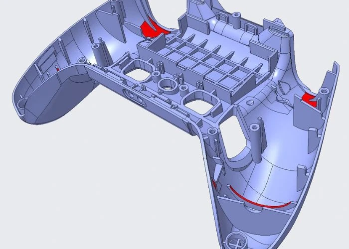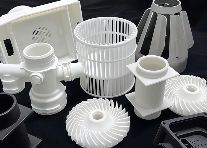

CNC machining thin plastic parts becomes difficult when the remaining structure can move under the same forces used to machine it. In our plastic prototyping work, we therefore plan thin-wall parts around changing rigidity, temporary support, cutting direction, machining sequence, and the condition of the part after release—not simply around the programmed toolpath.
Why CNC Machining Thin Plastic Parts Requires a Different Strategy
A thin plastic wall does not have to permanently warp before accuracy is lost. It may move only while the cutter is engaged, return after the tool passes, and still leave an incorrect wall thickness or surface position. This temporary movement makes thin-wall CNC plastic machining fundamentally different from machining a rigid block.
Thin-wall deflection is not the same as permanent deformation caused by residual stress, heat, or material removal. For the broader process controls we use for CNC machining plastic without warping or cracking, see our dedicated guide.
When we review this type of part, the first question is not simply whether a 1 mm, 1.5 mm, or 2 mm wall is machinable. Wall thickness alone tells us very little about how the structure will behave. A short wall supported by surrounding geometry may remain relatively stable, while a taller wall of the same thickness can move considerably when the cutting point is far from its support.
The manufacturing problem begins when the cutting force becomes large enough relative to the remaining structural stiffness. The wall moves away from its expected position, the cutter removes material from that displaced geometry, and the wall then springs toward its unloaded position. The CNC machine may have followed the programmed path accurately, but the finished geometry no longer represents that path.
This changes how we plan the process. Before programming, we look at where rigidity will disappear as material is removed, which walls will eventually become unsupported, where cutting forces will enter those walls, and which dimensions must remain accurate after the fixture is released. That tells us where the machining sequence itself must provide stability.
The First Decision Is When to Create the Final Wall Thickness
For many thin-wall parts, the most important process decision is not the final cutting parameter but when the wall is allowed to become thin. Once surrounding stock has been removed, the stiffness it provided cannot be recovered. We therefore avoid creating the weakest version of the geometry earlier than the following operations require.
Consider a housing machined from solid plastic stock. If we immediately machine the internal cavity to its final depth and bring the surrounding walls close to final thickness, those walls must withstand every later operation with much less support. Finishing an opening, machining an external feature, or establishing another face may then push against a structure that has already lost most of its original rigidity.
For a more sensitive geometry, we can reverse that logic. Heavy material removal and features that generate greater cutting loads are completed while useful stock still supports the part. The wall is progressively approached rather than immediately finished, with controlled allowance remaining until the operations most dependent on rigidity are complete. Only then do we bring the relevant surfaces toward their final relationship.
This does not mean every thin plastic part needs a complicated multi-stage process. If a short wall remains well supported and the required accuracy is moderate, additional stages may add cost without improving the result. We use staged wall formation when the final geometry itself would make the remaining operations less stable.
Temporary Material Can Become Part of the Machining Support
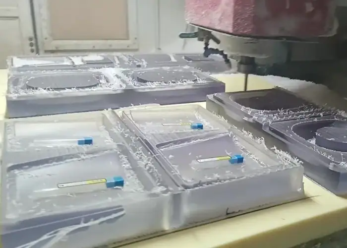
One technique we use on suitable plastic prototypes is to treat material that will eventually be removed as temporary structural support. A window may remain closed during earlier operations, part of a cavity may remain shallower than its final depth, or additional stock may be left behind a wall until nearby machining is complete.
The important point is that this stock must have a defined purpose. We do not simply “leave more material.” We determine what feature it supports, which cutting load it helps resist, and at what stage it can be removed without transferring the same problem to the final operation.
That last point matters. Temporary stock can create a new problem if removing it suddenly leaves a large flexible area for the final cut. It can also block tool access or make the final reference condition less reliable. For this reason, temporary support and its removal sequence must be planned together.
Support Must Follow the Cutting Area as Rigidity Changes
A fixture can hold the base of a part securely while the surface being cut remains free to move. For thin-wall plastic machining, we therefore distinguish between holding the workpiece and supporting the cutting zone. As the geometry changes, the distance and structural path between these two areas become increasingly important.
Imagine a deep plastic housing whose bottom is firmly located in a fixture. During early roughing, the stock is still thick enough for that support to work effectively. Later, as the cavity deepens and the wall becomes thinner, a cutter working near the upper edge may be applying force far from the supported base. The fixture has not become loose; the part between the fixture and cutter has become more flexible.
Our response is to review the direction of the cutting force and the path through which the remaining structure resists it. Depending on the geometry, this may involve distributed contact, shaped soft support, sacrificial backing, local support, or another low-distortion holding arrangement. We select these methods because of the force path, not because one fixture type is universally better for plastics.
Support also has to evolve with the part. A contact arrangement that works against a thick semi-finished wall can become inappropriate after that wall reaches final thickness. We therefore reassess support at the stages where major material removal changes the structural condition rather than assuming one fixture setup will behave identically throughout the entire operation.
Cutting Force Must Be Reduced Without Turning Cutting Into Rubbing
“Use lighter cuts” is common advice for thin-wall machining, but it is incomplete for plastics. Reducing instantaneous cutting load can limit deflection, yet an overly conservative cutting condition may produce poor chip formation and more rubbing. Our objective is therefore to reduce the force acting on the wall while keeping the cutter working efficiently.
In practice, we consider tool sharpness, radial engagement, cutting depth, tool reach, chip formation, and the direction of cutter engagement together. The exact values cannot be reduced to one universal feed or spindle-speed recommendation because a short supported wall and a tall open wall can respond very differently even in the same plastic.
The cutting state is also visible in the process. If chips stop forming cleanly, the surface begins to smear, or the cutter repeatedly rubs against a flexible wall, simply making the pass slower may make the situation worse. We adjust engagement and tool motion so that the finishing pass removes a controlled amount of stock rather than repeatedly loading the wall without efficient cutting.
This is also why the final allowance matters. Leaving excessive stock for the last pass can turn “finishing” into another high-load operation. Leaving almost nothing can encourage rubbing without providing enough material for a meaningful correction. Finishing allowance must match the remaining rigidity and the purpose of that final operation.
Toolpath Direction Changes How the Wall Responds to the Cutter
When a wall is flexible, we do not look only at where the cutter travels. We also consider where the cutting load is trying to push the wall. A toolpath that repeatedly loads a wall toward an unsupported direction can create a different dimensional result from one that allows the remaining structure or temporary support to resist more of that force.
The same principle affects machining height. Finishing one entire side of a tall thin wall before addressing the opposite side can progressively remove the support that the later cut needs. In suitable geometry, machining by controlled levels or balancing the progression on both sides can keep the wall more stable as its final section is formed. Toolpath systems themselves recognize this thin-wall problem; for example, depth-ordered finishing can avoid completely finishing one side before the other.
For us, the practical rule is not that one CAM strategy is always correct. We examine cutting -direction, remaining support, wall height, and the next operation together. The best toolpath is the one that creates the final geometry without repeatedly pushing an increasingly flexible wall into a temporary position.
Two-Sided Thin Walls Must Be Treated as One Dimensional Relationship
Many plastic housings and shells contain walls defined by an external surface and an internal cavity. We do not treat these as two unrelated machining jobs. Every time stock is removed from one side, the stiffness available to machine the other side changes, so both surfaces must be planned around the final wall between them.
Suppose the external cosmetic geometry is completed first and the internal cavity is then heavily roughed. As the cavity approaches final depth, the previously machined outer surface becomes the opposite side of a flexible wall. Any movement during internal finishing can now affect wall thickness and the relationship between the internal and external geometry, even though the outside itself is no longer being cut.
For a sensitive part, we can rough both relevant regions while sufficient section remains, leave controlled allowance on the surfaces defining the wall, and decide which surface should provide the more reliable reference for final machining. That decision depends on the actual part: an assembly interface, cosmetic exterior, controlled internal clearance, or another functional surface may have priority.
The key is not to follow a fixed “outside first” or “inside first” rule. It is to recognize that the two surfaces ultimately define one wall, and the process must preserve enough rigidity until that dimensional relationship can be finished reliably.
Deep Thin-Wall Housings Need a Changing Machining Strategy
A deep housing illustrates why thin-wall machining cannot be planned around one set of conditions. It begins as rigid stock, but every layer removed from the cavity changes wall stiffness, tool reach, chip evacuation, and support. By the time the final wall exists, the machining environment is very different from the first roughing operation.
During the early stage, the solid stock can tolerate the main cavity removal relatively well. As the cavity grows, however, the surrounding section becomes progressively less rigid and the cutter operates farther from the supported region. At the same time, chips have a longer path out of the cavity and the tool may require greater reach.
We therefore change the purpose of each stage. Early operations focus on efficient bulk removal without prematurely forming delicate features. Intermediate operations establish the cavity while retaining useful wall allowance and support. Near the final condition, cutting engagement is reduced, chip evacuation receives more attention, and critical wall relationships are approached with the remaining rigidity in mind.
Openings, narrow edges, mounting details, and other sensitive features may also be delayed if machining them earlier would remove support needed by the cavity operation. In other cases, part of a feature can be roughed earlier and only its final relationship completed later. The sequence follows what the structure can still support, not simply the order in which features appear in the CAD model.
Large Thin Plastic Panels Need Flatness Without Forced Geometry
Large thin panels add another challenge: low bending stiffness allows a local holding or cutting force to influence a much wider area. The machining goal is therefore not to make the panel look flat while constrained, but to establish a process that gives the required geometry when unnecessary fixture forces are removed.
If an initially bowed or flexible panel is forced firmly against a reference surface and then machined, the machine may produce a very consistent surface in that constrained condition. After release, however, the panel can return toward its natural condition. The machining result is repeatable, but the free-state flatness is not necessarily correct.
For these parts, we prefer support distributed over appropriate areas rather than using a few strong contacts to impose the desired shape. Material removal is also planned so that a large unsupported region is not created suddenly. When both faces contribute to the final thickness or flatness, the relationship between those operations is considered before either side is completely finished.
After critical machining, the panel must be evaluated in a representative released condition. If flatness changes significantly, we do not automatically increase clamping pressure on the next part. We first determine whether the process is controlling the panel or merely holding it temporarily in the geometry we want to see.
Critical Features Must Be Machined While Useful Support Still Exists
Finishing every critical feature last sounds logical, but it can be the wrong strategy for a flexible plastic structure. By the final stage, the material that could have supported a hole, narrow edge, mounting boss, or small rib may already be gone. We therefore choose feature timing according to stability, not a universal machining rule.
A critical mounting hole, for example, may need its final position established after the main body has reached a stable condition. Machining it completely at the beginning could allow later material removal to change its relationship with the surrounding geometry. In that case, late finishing is valuable.
A small feature close to an unsupported thin edge creates the opposite problem. Waiting until every surrounding pocket and opening has been completed may leave too little rigidity to machine that feature accurately. Here, we may create most of the geometry earlier while stronger support remains, leave a small controlled finishing allowance, and complete only the critical relationship later.
This gives us an important process option: a feature does not always need to be created and finished in the same operation. Separating those two moments allows us to use early rigidity for material removal while reserving final dimensional control for a more appropriate stage.
Feature Timing Should Follow Remaining Support, Not CAD Order
Before programming a sensitive feature, we consider what will physically support it at that moment and what later operations may still change its position. This is particularly important for slots close to an edge, mounting features on flexible walls, thin ribs, and openings whose surrounding stock will later disappear.
If early machining offers better support but later machining offers better positional accuracy, we can divide the feature between those stages. Rough geometry is established while the structure is stronger; final size or position is completed after the major structural changes have occurred.
This is one reason experienced CNC plastic machining is not simply a matter of translating CAD geometry into toolpaths. The order in which the final geometry appears can be just as important as the geometry itself.
Spring-Back Must Be Controlled Before We Compensate for It
When a flexible wall moves under the cutter and springs back afterward, it can be tempting to measure the error and compensate directly in the program. We avoid treating compensation as the first solution. If the deflection itself is not repeatable, a numerical correction can simply replace one dimensional error with another.
Suppose a wall is displaced during finishing and returns 0.15 mm from the expected position after the cut. Adding a corresponding toolpath offset may appear to solve the problem. But if the next part experiences different support, cutting load, stock condition, or fixture contact, its deflection may not be the same. The compensation has now become another uncontrolled variable.
Our first step is therefore to reduce the source of movement: improve support where the cutting load acts, reduce unnecessary radial load, revise the sequence, or postpone final wall formation. Once the wall behaves more consistently, we can measure the released geometry and determine whether a controlled finishing correction is still required.
This order matters. We stabilize the process before correcting the number. Compensation becomes useful only when the physical behavior producing the error is sufficiently repeatable to make that correction meaningful.
Inspection Must Separate Machining Accuracy From Free-State Accuracy
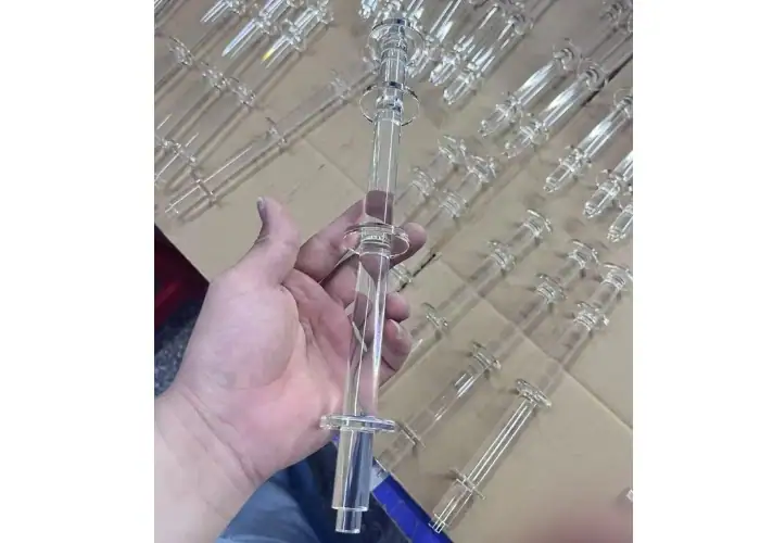
For thin-wall plastic prototyping, a dimension measured while the part is fully constrained does not always represent the geometry the engineer will receive. Our inspection therefore focuses not only on whether the cutter reached its programmed position, but also on whether critical geometry remains valid after machining forces and unnecessary fixture constraints disappear.
Depending on the project, we may focus on wall thickness, wall position, opening size, flatness, mating faces, or the relationship between holes located on flexible structures. The important dimensions are those that determine whether the prototype can provide the intended assembly or engineering information.
When a discrepancy appears after release, its direction can help us understand the process. A local wall-position change may point toward cutting-force deflection; a broader flatness change may require us to review support and material-removal sequence. Inspection therefore feeds back into machining rather than functioning only as a final pass/fail step.
For repeat parts, that information is especially valuable. Once the sensitive stage is identified, we can modify the support, allowance, or operation sequence before the next part reaches that condition instead of trying to correct the same error after machining.
How We Plan Thin and Stress-Sensitive Plastic Parts Before CNC Machining
Our process planning begins by asking how the part will change as it approaches its final geometry. For thin-wall parts, we review the finished CAD together with the machining states that must exist before it. This allows us to plan support and cutting around the part we are actually creating at each stage.
As a plastic prototype manufacturer, we first identify where major stock removal will reduce rigidity and which final walls, openings, or interfaces are most sensitive to that change. We then decide whether useful stock should remain temporarily and whether both sides of a wall need to be roughed before either is finished.
Next, we determine where cutting forces will act after the structure becomes thinner. Support and toolpath direction are planned around those areas, and high-load operations are completed before they unnecessarily depend on the weakest version of the geometry. Sensitive features are positioned in the sequence according to when adequate support and reliable reference geometry are both available.
Before final machining, we reassess the semi-finished part rather than assuming the original setup is still ideal. Critical wall relationships are then finished under the most stable practical condition, followed by inspection after unnecessary constraint has been removed.
In our experience, this is the real difference in machining difficult thin plastic prototypes. It is not simply using a slower feed or more clamps. It is knowing which material should not be removed yet, which feature should not be finished yet, and when the changing part needs to be evaluated again before machining continues.
What Should Engineers Identify Before CNC Machining Thin Plastic Parts?
We do not need engineers to redesign a part around our machining process, but we do need to understand which geometry must remain meaningful after release. A few clearly identified priorities are usually more useful than treating every thin surface as equally critical.
For a thin-wall project, we recommend identifying the final critical wall thickness, important mating surfaces, controlled openings, flatness requirements, and any holes or interfaces whose position affects assembly. Cosmetic surfaces should also be identified if temporary support or later finishing could affect them.
It is particularly useful to tell us which dimensions are required in the part’s free state. This helps distinguish a true functional relationship from a dimension that only appears stable while the workpiece is supported.
Where the geometry allows manufacturing flexibility, engineers can also indicate whether temporary machining stock or support is acceptable. We can then evaluate whether staged machining, additional setup work, or another support strategy is justified before quotation and programming.
Conclusion
Reliable CNC machining thin plastic parts requires us to control when the part loses rigidity, not simply reduce cutting parameters. By retaining useful support, managing cutting forces, sequencing thin-wall formation, and verifying critical geometry after release, we can keep difficult plastic prototypes more dimensionally predictable. If you have a thin-wall or stress-sensitive plastic part, send us your CAD files and critical requirements for manufacturing review.
FAQs
1. Why Do Thin Plastic Walls Deflect During CNC Machining?
Thin plastic walls have relatively low structural stiffness, so cutting forces can temporarily move the wall away from its expected position. If material is removed while the wall is displaced, it may spring back after the cutter passes and leave a dimensional error. We therefore control both the cutting load and the support available at the cutting location.
2. Should Thin Plastic Walls Be Machined to Final Thickness Early or Late?
There is no fixed rule, but sensitive walls are often kept thicker while operations that depend on rigidity are completed. We decide when to create final thickness according to wall geometry, surrounding support, tool access, and the remaining machining operations. The objective is to avoid making the part unnecessarily flexible too early.
3. How Do You Support Thin Plastic Parts During CNC Machining?
We position support according to where cutting forces act rather than simply adding more clamping pressure. Depending on geometry, this can involve distributed fixture contact, shaped support, sacrificial backing, or temporarily retained material. The support strategy may also change after roughing because the semi-finished part no longer has the stiffness of the original stock.
4. Does Toolpath Direction Affect Thin-Wall Plastic Machining?
Yes. Toolpath direction changes how cutting forces act on a flexible wall and whether the remaining structure can resist them. We consider cutting direction together with wall height, support position, cutter engagement, and the next machining operation rather than selecting a toolpath based only on geometry.
5. Why Does a Thin Plastic Wall Change Size After the Cutter Passes?
The wall may deflect while it is under cutting load and then spring back when that load disappears. The cutter therefore removes material from a temporarily displaced surface. We first reduce this movement through support, machining sequence, and cutting-force control before considering dimensional compensation.
6. How Should Thin Plastic Parts Be Inspected After CNC Machining?
Critical geometry should be checked under a representative released condition, particularly wall thickness, wall position, flatness, openings, mating surfaces, and assembly-related hole relationships. For sensitive parts, comparing constrained and free-state behavior can also help identify whether an error comes from machining, support, or temporary deflection.