
Machining High Performance Plastics becomes more predictable when the material specification is treated as part of the manufacturing problem rather than the entire problem. In our plastic prototyping work, engineers often come to us with PEEK, PPS, PEI, or another grade already specified. Our job is to determine how that material behaves in the actual geometry, then build the tooling, machining sequence, workholding, finishing, and inspection plan around the finished part requirements.
From a Specified Material to a Practical CNC Manufacturing Plan
Once an engineer has specified a high-performance plastic, the next manufacturing question is not whether the material is “difficult to machine.” We need to understand which characteristics of the material will actually matter after it is combined with the geometry, tolerance, surface, and assembly requirements of the part.
For example, a compact PEEK component with moderate tolerances may remain rigid throughout machining and require a relatively direct process. The same material used for a housing with a deep cavity, thin remaining walls, precision mounting holes, and large stock removal presents a different manufacturing problem. As the cavity is opened, the workpiece loses support; as the remaining section becomes thinner, the clamping condition changes; and if critical holes are finished too early, later material removal can affect the relationship those features were intended to maintain.
This is why we do not begin CNC plastic machining by assigning a fixed process to a material name. We first review the exact grade, stock condition, CAD geometry, critical dimensions, quantity, visible surfaces, and mating interfaces. Those factors tell us whether the part needs a straightforward machining route or whether roughing, refixturing, stabilization, controlled finishing, or additional inspection should become part of the plan.
The distinction matters because high-performance plastic machining should not automatically mean more processing. The objective is to identify where the part is likely to become difficult to control and solve that problem before it affects the finished prototype.
Machining High Performance Plastics Starts With Identifying the Real Process Risk
The material grade influences machining, but it rarely acts alone. In practice, the more useful question is how the material interacts with the geometry being created. That connection determines whether tooling, heat, material removal, or workholding becomes the dominant manufacturing concern.
Material Grade Changes the Cutting Condition
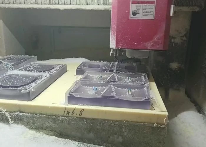
A material specification such as PEEK or PPS is only the first level of information. An unfilled grade and a glass- or carbon-filled version may share the same base polymer, but they should not automatically be treated as the same cutting condition. Reinforcement can increase abrasiveness and accelerate tool wear, which makes cutting-edge condition more important when machining precision edges, controlled surfaces, or multiple parts that need consistent results. This distinction between unfilled and reinforced PEEK is also reflected in current machining guidance.
Our response is not simply to specify a “stronger” tool. We consider how long the cutting edge must maintain its condition, which features will be machined later in the tool cycle, and whether progressive wear could change burr formation or surface consistency before obvious tool failure occurs. For abrasive grades, changing a tool earlier can be less costly than repairing an expensive part after edge quality or a critical feature has already deteriorated.
Geometry Determines Whether That Cutting Behavior Becomes a Problem
The same material behavior can have very different consequences depending on geometry. Moderate tool wear may have little effect during heavy stock removal, but the same wear becomes more important when the cutter moves into a final visible edge or a controlled mating feature. Likewise, localized heat that is manageable in a thick section may become more significant once the same workpiece has been opened into a thin wall or narrow rib.
For this reason, we prefer to evaluate machining risk by stage rather than label the entire part “difficult.” The early roughing stage may prioritize efficient and stable stock removal, while later operations shift toward protecting thin sections, final surfaces, and datum-related features. The machining strategy therefore changes as the part itself changes.
Tooling, Chip Removal, and Heat Control Need to Be Planned Together
Tooling and thermal control are often discussed separately, but on the machine they are part of the same cutting condition. A sharp edge removes material efficiently; the resulting chip carries part of the heat away; effective evacuation prevents that hot chip from remaining in the cutting zone. When one part of this system deteriorates, the others are affected as well.
We Correct the Source of Heat Instead of Only Slowing the Machine
High-performance plastics generally transfer heat less efficiently than metals, so poor cutting conditions can concentrate heat around the tool and workpiece. Current PEEK machining guidance repeatedly emphasizes sharp cutting edges, controlled engagement, and effective chip evacuation for this reason.
If a machined surface begins to smear or local heat increases, simply reducing feed is not always the right correction. A worn edge may be rubbing instead of cutting; chips may be recutting inside a deep pocket; or a toolpath may keep the cutter engaged in one region for too long. In these cases, lowering the feed without correcting the cause can increase contact time and leave the original problem unresolved.
We therefore look at tool condition, chip formation, chip evacuation, cutting engagement, and the geometry being machined before adjusting the process. Cooling or air assistance can then support the cutting strategy rather than compensate for an inefficient one. The objective is not simply to keep the machine “cool”; it is to maintain a cutting condition that produces the required surface and geometry consistently.
Machining Sequence Is Often the Solution When Material Removal Changes the Part
The most important change during CNC machining may not be the cutting parameter at all. A solid blank can begin as a stable workpiece and gradually become a thin-walled, less rigid component as stock is removed. When that happens, machining order, remaining allowance, and the timing of critical features become more important than repeatedly adjusting feeds and speeds.
Roughing Should Create a Stable Basis for Final Machining
Consider a housing machined from a high-value plastic block. If a large internal cavity must be removed, we first need to establish reliable machining references and remove the major stock without prematurely finishing every precision interface. Where the geometry requires it, we retain controlled allowance on critical areas so that those surfaces can be completed after the workpiece is much closer to its final condition.
This sequence gives us an opportunity to reassess the workpiece after the largest structural change has occurred. If the part remains stable, finishing can continue directly. If the geometry or project tolerance makes further stabilization appropriate, that decision can be made before the final features are locked in. Current machining guidance for precision PEEK parts similarly describes roughing followed by stabilization or stress relief and then final machining where the application justifies it.
The important point is that roughing and finishing serve a manufacturing purpose beyond simply dividing heavy and light cuts. Roughing creates the approximate final structural condition; finishing establishes the dimensions, interfaces, and surfaces that must be correct in that condition. This is particularly valuable for precision holes, locating features, mating faces, and other relationships that should not be completed before major material removal is finished.
Annealing or Stabilization Should Solve a Defined Risk
This is also where annealing needs to be considered carefully. Some published machining guides recommend annealing strongly for precision PEEK, while other guidance notes that it is not automatically required and becomes more relevant for long parts, thin walls, heavy material removal, or demanding tolerances. That difference is useful because it reinforces a practical manufacturing principle: the process should follow the part rather than a universal rule.
For a simple component that remains rigid and has moderate tolerances, adding an intermediate thermal process may only increase lead time. For a heavily machined precision component, however, allowing the workpiece to stabilize—or applying an appropriate stress-relief process when justified—before final machining can prevent us from using finishing cuts to chase dimensions on a part that is still changing.
The additional step must also be controlled correctly. A thermal process that is unnecessary, poorly specified, or incompatible with the exact material grade can introduce cost or new uncertainty instead of reducing it. We therefore treat stabilization as one possible tool within the manufacturing plan, not as proof that the process is more advanced.
Workholding Must Change as the Workpiece Changes
Workholding is closely connected to machining sequence. The fixture that holds a thick blank securely during roughing may become unsuitable after deep cavities are opened and the remaining walls lose stiffness. Rather than asking only how tightly a part should be clamped, we need to consider where support is needed at each stage and how the clamping load is transmitted through the changing geometry.
During early stock removal, the blank usually provides enough section thickness to resist cutting forces. Once that material is removed, continuing to apply the same force at the same locations can load a thinner wall or distort a surface that has now become part of the final geometry. At that point, changing support locations, increasing the supported area, reducing localized pressure, or using an alternative finishing fixture can provide better control than simply lowering machining forces.
However, greater support is not always better. If a flexible part is forced flat against a fixture, it may measure correctly while clamped and move after release. That creates a misleading sense of machining accuracy. The fixture must stabilize the workpiece against cutting forces without forcing it into a geometry that it cannot retain naturally.
This is why we sometimes use different workholding logic for roughing and finishing. The fixture evolves with the workpiece so that the machining condition remains appropriate as the part approaches its final form. Workholding is therefore not an isolated setup issue; it is part of the same process strategy as material removal and final feature machining.
Critical Features Should Be Finished When the Part Is Ready for Them
Once the major material removal and workholding strategy are established, the next question is when to finish the features that actually determine whether the part works with the rest of the prototype. Precision holes, locating bosses, mating faces, bearing positions, controlled gaps, and assembly interfaces should not automatically be completed at the earliest possible operation.
If a precision mounting hole is finished before a nearby cavity removes most of the supporting stock, the hole may be dimensionally correct when produced but no longer maintain the same relationship after the surrounding structure changes. A more reliable approach is often to complete the large structural changes first, re-establish the relevant datum condition if necessary, and then finish the interface from the geometry that will actually exist in the final part.
This does not mean every critical feature must be machined last. Some features may be needed as manufacturing datums or setup references earlier in the process. The important distinction is between features that help us manufacture the part and features whose final relationship must be protected. Good process planning decides which role each feature plays before the toolpath is finalized.
For engineers, this is one reason why clearly identifying critical dimensions and mating interfaces in the drawing is valuable. It gives the manufacturer enough information to arrange the machining sequence around the features that matter most rather than treating every CAD surface as having the same manufacturing priority.
Surface Quality Should Be Built Into CNC Machining Before Finishing
For cosmetic or presentation prototypes, finishing should refine the surface produced by CNC machining rather than repair preventable machining damage. This becomes especially important when a visible surface is close to a precision edge, mating interface, or dimensional feature, because aggressive corrective finishing can improve appearance while unintentionally changing geometry.
Before machining, we therefore identify which surfaces will remain natural, which will be polished, and which will continue into painting, silk screening, UV coating, or another specified finish. This information can affect toolpath direction, finishing allowance, edge protection, and even the order in which some visible areas are machined. A surface that will later be polished does not need to be treated the same way as a hidden structural pocket, but it should not be left with unnecessarily deep marks simply because polishing follows.
The same reasoning applies to hand finishing. Removing burrs or blending a cosmetic surface should not erase a controlled edge or change a mating dimension. By planning CNC plastic machining and surface finishing as connected operations, we reduce the amount of corrective work required after machining and make the final appearance more predictable.
For us, the manufacturing target is simple: machining should leave a surface that finishing can improve, not a damaged surface that finishing must rescue.
High-Value Materials Need Better Decisions Before More Operations
The cost of high-performance plastic stock changes the consequence of a manufacturing mistake, but it should not automatically change a simple part into a complicated process. The most effective risk reduction often happens before the first setup, when the manufacturing team still has the opportunity to confirm the information that will determine the entire machining route.
We want the latest CAD revision to agree with the drawing, the exact material grade to be confirmed, and the critical dimensions, visible surfaces, mating interfaces, quantity, and finishing requirements to be clear before valuable stock is committed. If a critical interface is discovered only after roughing, or a cosmetic surface is identified after the wrong fixture has already marked it, the problem is no longer just an engineering clarification—it has become material and machine time that may need to be repeated.
The same principle prevents overprocessing. A straightforward part with normal tolerances does not become better simply because we add annealing, multiple setups, intermediate inspections, and additional finishing stages. Each operation should have a manufacturing reason. If it protects a critical requirement or removes a defined risk, it belongs in the process; if it does neither, it may only add cost and another opportunity for variation.
This is particularly important in prototype manufacturing, where quantities are often low and the objective is to obtain useful engineering information quickly. A controlled process is more valuable than an unnecessarily elaborate one.
CNC Manufacturing Solutions for Common High Performance Plastic Part Conditions
The manufacturing conditions discussed above are connected rather than independent. A thin wall may require different workholding, but that workholding must not introduce clamp distortion; large material removal may justify separate roughing and finishing, but the finishing stage still needs reliable datums. The table summarizes these relationships from a manufacturing-solution perspective.
| Part Condition | What Changes During Machining | Manufacturing Response | Secondary Risk to Control |
| Reinforced grade | Cutting edge wears faster | Monitor tooling according to feature requirements | Burrs and surface inconsistency |
| Large material removal | Workpiece approaches a different structural state | Rough first and finish critical areas later where needed | Datum shift and remaining allowance |
| Thin walls or deep cavities | Rigidity decreases | Adapt support and workholding as geometry develops | Clamp-induced deformation |
| Precision interfaces | Final relationship becomes more important than individual dimensions | Finish from the appropriate final datum condition | Later machining affecting the interface |
| Cosmetic surfaces | CNC condition affects finishing effort | Protect visible surfaces during machining | Excessive sanding changing geometry |
| High-value stock | A process error becomes expensive | Resolve key manufacturing decisions before cutting | Overprocessing and unnecessary cost |
The value of this approach is that every manufacturing response is checked for the new problem it might create. That is more useful than treating Machining High Performance Plastics as a collection of isolated rules.
Inspection Should Close the Same Manufacturing Loop
Inspection should confirm the requirements that shaped the machining strategy in the first place. If a project required a special sequence to protect a mating interface, that interface should receive appropriate dimensional attention. If visible surfaces influenced machining and finishing decisions, visual inspection should confirm that the final surface has been achieved without compromising nearby edges or interfaces.
This means we do not view inspection as a separate quality-control chapter added after manufacturing. Dimensional inspection, visual review, and trial assembly where applicable are extensions of the decisions made during manufacturing review. The drawing tells us what must be controlled; the machining plan determines how we intend to achieve it; inspection verifies whether that plan produced the required result.
For a plastic prototyping project involving several mating parts, trial assembly can be particularly useful because it shows whether locating features, gaps, interfaces, and fastener positions work together as intended. This remains different from complete product functional testing; the objective is to verify the manufactured prototype and its relevant assembly relationships.
How UForProto Builds the CNC Process Around the Part
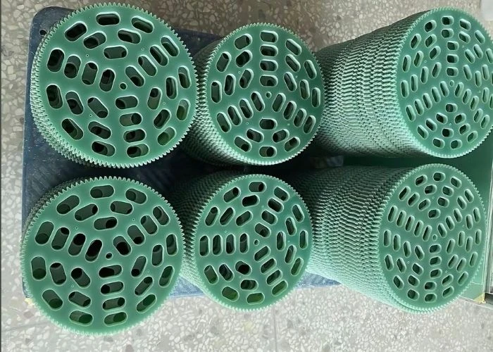
As a direct plastic prototype manufacturer, we prefer to make manufacturing decisions from the finished-part requirements backward. Material is one input, but geometry, critical dimensions, surface condition, assembly relationships, and prototype purpose determine how that material should actually move through the workshop.
Manufacturing Review Defines the Process Before Machining Begins
When we receive CAD files and drawings, we first identify what must remain correct at the end of manufacturing. From there, we determine suitable machining references, major material-removal stages, workholding conditions, critical features, visible surfaces, and any finishing or assembly requirements that will affect the CNC route. This lets us resolve the process as a connected sequence rather than making one decision at each machine operation.
If the geometry remains stable, we keep the process direct. If large material removal changes the workpiece, we can separate roughing and finishing. If a reinforced grade creates greater tool wear, tooling control is strengthened around the features that matter. If a visible surface requires finishing, CNC machining prepares it for that process rather than leaving avoidable corrective work for later.
This is the principle behind our approach to Machining High Performance Plastics: use additional process control where the part requires it, and avoid adding complexity where it does not improve the result.
CNC Machining, Finishing, and Assembly Should Remain Connected
For projects that continue beyond individual machined parts, we also consider what happens after CNC machining. A cosmetic housing may need sanding and painting; another component may require silk screening or another specified finish; several parts may need trial assembly before the prototype is completed. These downstream requirements can influence which surfaces need protection and which dimensions should receive priority during machining.
At UForProto, CNC plastic machining, surface finishing, and complete prototype assembly can be connected within the same plastic prototyping project. The advantage is not simply having more services under one roof. It is that decisions made in machining can account for what the part needs during finishing and assembly, reducing unnecessary corrections between manufacturing stages.
Conclusion
Machining High Performance Plastics requires a CNC process matched to the actual part, not just the material name. Once the grade and key requirements are clear, the manufacturing strategy should focus only on the controls that protect critical dimensions, surfaces, and assembly features. This helps reduce unnecessary complexity, rework, and material waste. If you have a high-performance plastic prototype project, you can send us your CAD files, drawings, material grade, quantity, and key requirements for manufacturing review and quotation.
FAQs
1.What Information Should I Provide for Machining High Performance Plastics?
We recommend providing the latest 3D CAD, relevant 2D drawings, exact material grade, quantity, critical tolerances, surface requirements, and any assembly information that affects the part. Together, these allow us to evaluate the actual manufacturing route rather than quote from the material name alone.
2.Do PEEK, PPS, and PEI Require Different CNC Machining Strategies?
Yes. However, the polymer name is only part of the decision. Exact grade, reinforcement, geometry, material-removal volume, tolerance, and surface requirements can change the machining strategy significantly, so we evaluate them together before defining the process.
3.Do Reinforced High Performance Plastics Require Different Tooling?
Often, yes. Glass- and carbon-filled grades can be more abrasive and accelerate cutting-edge wear. Tool selection and replacement strategy should therefore reflect the material grade, production quantity, and features being machined rather than waiting for obvious tool failure.
4.When Should Rough and Finish Machining Be Separated?
They are worth separating when major material removal changes the structural condition of the workpiece or when critical features are better finished after that change has occurred. Straightforward parts with moderate tolerances may not need the same multi-stage route.
5.Is Annealing Always Required When Machining High Performance Plastics?
No. Published guidance varies, and the need depends on the exact material, stock condition, geometry, amount of material removed, and tolerance requirements. We treat annealing or stress relief as a solution for a defined stability risk rather than an automatic step for every high-performance plastic part.
6.Can High Performance Plastic Parts Be Finished and Assembled After CNC Machining?
Yes, where the selected material and project requirements are suitable. Planning finishing and assembly before machining allows visible surfaces, critical edges, and mating interfaces to be protected throughout the manufacturing route instead of corrected after the parts are complete.