
Plastic Manufacturing Tolerances are most useful when they communicate which geometric relationships must be preserved in the finished prototype. In our plastic prototyping work, I do not read a drawing simply as a collection of ± values. I look for the dimensions, datums, fits, feature relationships, and inspection requirements that determine whether the CNC-machined plastic part will actually perform its intended engineering role.
Start With the Functional Relationship, Not the Smallest Tolerance
When I review a tolerance drawing for a prototype, the first question is not which dimension has the smallest ± value. I first determine which features control fit, alignment, motion, mounting, or assembly. Those relationships tell us where dimensional variation can actually change the engineering conclusion obtained from the prototype.
For a broader discussion of how tolerance decisions interact with manufacturability, machining access, and prototype requirements, see our guide to DFM for plastic prototyping.
A drawing may contain dozens of dimensions, but they do not all carry the same manufacturing consequence. A tightly controlled recess may be relatively independent, while the relationship between two mounting locations can determine whether an entire customer-supplied module can be installed. In that case, the second requirement deserves greater manufacturing attention even if its numerical tolerance appears wider.
This is why I prefer engineers to distinguish between drawing dimensions and critical manufacturing dimensions. The purpose is not to remove dimensions from the drawing or loosen specifications arbitrarily. It is to make the functional hierarchy visible enough that programming, machining, and inspection all protect the same result.
Critical Does Not Always Mean Tight
A critical dimension is one whose deviation can change how the prototype fits, moves, aligns, seals, mounts, or interfaces with another component. A tight tolerance only describes the permitted numerical variation. These two concepts often overlap, but they are not identical.
For example, an isolated decorative recess might be specified at ±0.05 mm, while the distance between two locating bosses is ±0.10 mm. If those bosses position a display or mechanical module, their relationship may be more important to prototype validation than the tighter decorative feature.
When this functional priority is clear, we can concentrate machining control and inspection on the dimensions that carry engineering risk rather than assuming every small tolerance number deserves the same process strategy.
Specify the Relationship the Prototype Actually Needs to Control
Once critical features are identified, the next step is to define what must be controlled about them. Size alone is often not enough. In many CNC plastic machining projects, the engineering result depends on where a feature is located, how it relates to another feature, or whether several features establish a common interface.
This is especially common in housings, covers, brackets, internal supports, display openings, connector locations, and mechanical prototype parts. A hole may have the correct diameter but still fail to align with a mating component. A rectangular opening may have the correct width and height while sitting incorrectly relative to a display or surrounding cosmetic boundary.
For us as a manufacturer, these are different problems. Feature size determines how much material should remain around that individual geometry. Feature location determines where it must exist. A relationship between several features determines whether they work together. The drawing should make the requirement that matters most to the prototype identifiable.
Size Tolerance and Position Control Solve Different Problems
Consider four mounting holes used to install a customer-supplied component. Controlling only the diameter confirms whether each fastener can physically enter the hole. It does not fully confirm whether the four holes reproduce the mounting pattern required by the component.
If the mounting pattern is the real engineering requirement, I need a drawing that allows that relationship to be manufactured and inspected from a meaningful reference. Otherwise, four individually acceptable holes can still create an unacceptable assembly.
The same logic applies to slots, bosses, connector cutouts, bearing locations, and display openings. Before assigning a tighter size tolerance, engineers should ask whether size itself is the problem they need to control—or whether location and relationship are actually driving prototype performance.
Build Critical Dimensions Around a Consistent Datum Structure
Once several critical features must work together, they need a common geometric language. This is where a clear datum structure becomes valuable. In prototype manufacturing, I use datum information to understand how important features are intended to relate to the part and to each other—not simply as a drawing convention.
The strongest datum is usually one that represents a meaningful physical relationship in the finished product. A mounting plane, locating bore, functional edge, or repeatable interface can often provide better manufacturing information than an arbitrary cosmetic boundary.
What matters is consistency. If the engineering drawing defines an opening from one reference, the mating feature from another, and the inspection method introduces a third unrelated reference, each result may look acceptable individually while the complete relationship becomes difficult to evaluate.
A good datum structure reduces that ambiguity. It gives us a common reference for understanding where critical features belong and provides inspection with a way to verify the same engineering relationship after machining.
Design, Machining, and Inspection Should Speak the Same Datum Language
The design datum expresses engineering intent. The machining reference tells us how that intent will be transferred to the physical workpiece. The inspection reference determines how the finished relationship will be verified. These do not always have to be the same physical surface, but they must remain traceably related.
If a functional mounting face is Datum A on the drawing, for example, but manufacturing must initially hold the part from raw stock elsewhere, that is not automatically a problem. What matters is that the machining route eventually establishes Datum A correctly before dependent critical features are finalized.
This is more useful than forcing every operation to use the same physical setup. The objective is to preserve the datum relationship, not to make manufacturing imitate the drawing literally.
This becomes more challenging on oversized components, where datum transfer and multiple machining setups must be managed across a much larger geometry, as discussed in our guide to large plastic prototype machining.
Use Tolerance Chains Where Several Features Create One Result
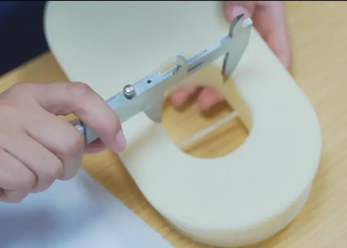
Some prototype problems cannot be understood by looking at one dimension at a time. A final gap, clearance, alignment, or interface position may depend on several dimensions from one part—or several different parts. In these cases, the engineering question is not whether every dimension passes individually, but how their permitted variation combines.
This is where tolerance-chain thinking becomes valuable. I am not suggesting that every prototype requires a complex statistical tolerance analysis. For many prototype projects, the important first step is simply identifying where several acceptable variations can accumulate in the same direction and change the final result.
For example, the position of a display inside a housing may depend on the housing opening, internal locating bosses, bracket geometry, and display mounting features. Each dimension can remain within its own limit while the final visible alignment approaches an unacceptable condition.
If the prototype is intended to evaluate that alignment, the drawing should not leave the complete relationship hidden inside several unrelated dimensions. The engineer and manufacturer should know which dimensional chain produces the final condition that matters.
Control the Result Instead of Tightening Every Link in the Chain
When accumulated variation creates a risk, the first reaction should not always be to tighten every contributing dimension. That can increase CNC machining and inspection effort without addressing which relationship actually dominates the result.
I prefer to identify the dimensions that have the strongest influence on the final interface. Sometimes one locating relationship can be controlled more directly. In other cases, a common datum or assembly-level requirement communicates the engineering need better than several independently tightened dimensions.
This is particularly useful in plastic prototyping because the objective is usually to obtain reliable engineering information quickly. Precision should be concentrated where it improves that information, not distributed uniformly across every feature in the dimensional chain.
Define Fits and Clearances by What the Prototype Must Demonstrate
Many critical dimensions exist because two components must interact. In these cases, I find it more useful to begin with the required physical relationship than to specify two isolated dimensions and assume the desired fit will appear automatically.
A shaft and bore, locating pin and hole, removable cover, sliding component, or nested housing all require some form of clearance or interference relationship. The appropriate condition depends on what the prototype is expected to demonstrate: easy assembly, repeatable location, controlled movement, visual gap, or another engineering objective.
For CNC plastic machining, this distinction matters because the nominal dimensions of both components contribute to the final fit. If the engineer specifies each dimension independently without considering the intended relationship, both parts can satisfy their drawings while the physical fit sits near an undesirable end of the combined tolerance range.
This is why I prefer drawings and project information to communicate the intended fit, not merely the individual numbers that create it. We can then understand which component or feature should carry the tighter control and how the relationship should be verified.
Separate Machining Dimensions From Final-Condition Requirements
A prototype drawing may describe the finished component, while manufacturing reaches that condition through several operations. For parts that require polishing, painting, bonding, or assembly, I need to know which critical requirements belong to the machined geometry and which apply only after the prototype reaches its final condition.
This does not mean creating a separate tolerance system for every manufacturing step. The practical objective is to identify features that can still change after CNC plastic machining. A painted mating interface, polished transparent edge, bonded joint, or assembled gap may not have reached its final state when the cutter stops.
When this distinction matters, we plan the control point accordingly. A functional interface that must remain unchanged may be protected during finishing. A polished area near a precision edge may require controlled hand finishing. A final gap may need to be verified only after the related components are assembled.
This keeps inspection aligned with engineering intent. We still inspect machining where machining creates the requirement, but we do not mistake an intermediate condition for the finished result the drawing is intended to control.
Make Inspection Requirements Match the Critical Dimension
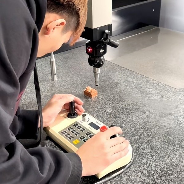
A tolerance is only useful if the finished feature can be verified in a way that represents the engineering requirement. For straightforward dimensions, conventional measurement may be sufficient. For feature relationships, positions, or assembly conditions, the inspection approach needs to reflect what the drawing actually controls.
I therefore prefer engineers to specify special inspection requirements only where they add engineering value. If a critical relationship requires a particular datum setup, inspection condition, measurement location, or report, that information should be clear. For ordinary dimensions, unnecessary measurement instructions can make the drawing harder to use without improving the result.
The same principle applies to flexible or condition-sensitive plastic parts. If the requirement applies to the part in its free state, the inspection should not unknowingly force it into another geometry.
Material condition, residual stress, temperature, and moisture can introduce additional dimensional changes; we examine these factors separately in dimensionally stable plastics for CNC machining.
If a dimension represents an assembled condition, inspecting the individual component alone may not answer the intended question.
Good tolerance communication therefore connects three things: what must be controlled, what reference defines it, and how we know the finished part satisfies it.
How We Review Critical Tolerances Before CNC Plastic Machining
As a direct plastic prototype manufacturer, our tolerance review begins by understanding the engineering relationships behind the drawing. We do not automatically question every tight tolerance, nor do we simply accept every number without considering how the related features work together.
For a new CNC plastic machining project, I first identify the interfaces that determine fit, location, motion, or assembly. I then review whether the dimensions and datums communicate those relationships clearly. Where several dimensions contribute to one result, I consider the dimensional chain rather than evaluating each number in isolation.
If the final condition depends on finishing or assembly, that is included in the control plan before manufacturing begins. Inspection is then placed where the relevant requirement actually becomes meaningful. This prevents us from proving an intermediate dimension while overlooking the finished relationship the engineer wanted to validate.
When something is unclear, the most useful manufacturing feedback is specific. Instead of saying only that a tolerance is “too tight,” we should explain what makes the requirement difficult to control, what relationship appears to be critical, and whether another way of dimensioning or referencing it would communicate the engineering intent more reliably.
Tolerance control is only one part of prototype quality. Machining strategy, process handoffs, surface finishing, inspection, and assembly can also affect the final result; we examine how these stages work together in plastic manufacturing for prototypes.
Useful Tolerance Feedback Should Lead to a Manufacturing Decision
When we identify a tolerance concern, the discussion should lead somewhere practical. Depending on the requirement, the solution may be to preserve the tolerance exactly as drawn, clarify the datum, control a feature relationship more directly, change the inspection condition, or protect a critical interface during finishing.
The correct response depends on why the dimension exists. This is why I do not treat tolerance review as a simple “achievable or unachievable” judgement. A manufacturer should understand the engineering objective first and then determine the most reliable way to preserve it through machining and inspection.
For engineers, this produces more useful feedback than receiving a generic tolerance warning. For us, it creates a clear manufacturing target before the first part enters the machine.
Conclusion
Effective Plastic Manufacturing Tolerances should describe the relationships that make a prototype work, not simply add tighter ± values to a drawing. By identifying critical features, using consistent datums, considering tolerance chains, defining intended fits, and matching inspection to the final condition, engineers can communicate dimensional requirements more clearly. In our plastic prototyping work, this gives us a stronger basis for planning CNC plastic machining and protecting the features that matter most. If your prototype contains critical fits or dimensional relationships, you can send us the CAD files and drawings for manufacturing review.
FAQs
1. What Are Plastic Manufacturing Tolerances?
Plastic Manufacturing Tolerances define the permitted dimensional variation of a manufactured plastic part. For prototype manufacturing, they should also communicate which feature size, location, fit, clearance, or geometric relationship must remain controlled so that the physical prototype provides useful engineering information.
2. Does a Critical Dimension Always Need a Tight Tolerance?
No. A critical dimension is important because it affects function, fit, alignment, motion, or assembly. The required tolerance should reflect how much variation that relationship can accept. Making the number smaller than necessary can increase manufacturing and inspection effort without improving prototype validation.
3. Why Are Datums Important for CNC Plastic Machining Tolerances?
Datums establish the reference from which critical feature relationships are created and inspected. A consistent datum structure helps design, CNC plastic machining, and inspection evaluate the same engineering relationship rather than independently controlling dimensions from unrelated references.
4. What Is a Tolerance Chain in a Plastic Prototype?
A tolerance chain occurs when several dimensions contribute to one final result, such as a gap, alignment, clearance, or component position. Even when each individual dimension is acceptable, their combined variation can move the final relationship toward an undesirable condition.
5. Should Prototype Tolerances Apply Before or After Surface Finishing?
It depends on the engineering requirement. A critical machined interface may need to remain protected during finishing, while a painted gap or polished transparent edge may only reach its final condition after finishing. The drawing and project requirements should make the relevant final state clear.
6. What Should Engineers Include on Drawings for Critical Prototype Dimensions?
The drawing should clearly identify critical dimensions, meaningful datums, feature relationships, intended fits or clearances, and any special inspection requirements that affect prototype validation. Relevant assembly information should also be provided when the dimensional requirement depends on another component.