
A datum in GD&T is more than a letter such as A, B, or C on an engineering drawing. It establishes the reference from which important geometric relationships are defined and verified. In CNC plastic machining, I use datum information to understand how a designer expects critical features to relate to the functional part. A well-planned datum GD&T system helps connect design intent with manufacturing, inspection, and final assembly. Poor datum selection can make a drawing measurable without necessarily making the resulting part functionally meaningful.
What Is a Datum in GD&T?
A datum is a theoretically exact reference used to establish geometric relationships on a part. Depending on the application, it may be a plane, axis, line, point, or a combination of these references. The important distinction is that the datum itself is theoretical; the physical part contains the feature from which that datum is derived.
For example, suppose a machined plastic housing has a flat mounting surface identified as Datum Feature A. The physical surface is not the datum itself. Instead, inspection equipment contacts or evaluates that real surface and establishes a theoretically exact datum plane from it. Other controlled features can then be located or oriented relative to that reference.
This distinction becomes especially important when a hole, slot, or cylindrical feature is used as a datum feature. A bore is a real physical feature, but the datum derived from it may be a theoretically exact axis. Understanding this prevents the physical surface and its derived reference from being treated as the same thing.
Datum and Datum Feature Are Not the Same Thing
In a drawing review, I separate these two terms carefully. A datum feature is the real, tangible surface or feature of size on the manufactured part. A datum is the theoretically exact reference derived from that feature. Measurement equipment, fixtures, gauge pins, surface plates, or mathematical fitting can simulate the datum during inspection.
This difference has practical consequences. If Datum Feature B is a bore, I need to understand whether the drawing intends the derived axis to establish the relevant reference. If it is a planar mounting face, the resulting reference may instead be a datum plane. The physical feature determines how the theoretical reference can be established.
Why Does a Datum Matter for CNC Machined Parts?
A part can contain many accurate dimensions and still fail to control the relationship that matters in assembly. A datum gives geometric requirements a meaningful reference. For CNC machined parts, I use that reference to understand which surfaces, axes, holes, or mating features establish the functional relationship that the designer actually needs.
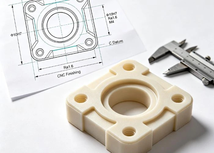
A Ø5 mm hole dimension tells me the required size of the hole. It does not, by itself, fully describe where that hole must sit relative to the functional structure of the part. When its position is controlled relative to Datums A, B, and C, the drawing communicates a different level of information: the hole must exist in a defined relationship to those references.
This is why I view datum information as a communication link between design, manufacturing, and inspection. The designer defines the functional reference system, the manufacturer plans how to produce the required relationships, and inspection recreates the specified references to determine whether the finished part satisfies the drawing.
When those datum references are used to define critical dimensions and geometric requirements, they also become an important part of how plastic manufacturing tolerances are specified and verified on the finished part.
How Does a Datum Reference Frame Control a Part?
One datum is not always enough to establish the complete reference needed for a geometric requirement. GD&T can combine primary, secondary, and tertiary datum references into a Datum Reference Frame (DRF). The DRF creates the coordinate framework from which specified geometric characteristics are evaluated and constrains the degrees of freedom required by the application.
A free part can translate in three directions and rotate around three axes, creating six degrees of freedom. A properly constructed datum reference frame constrains the degrees of freedom needed to establish the intended measurement relationship. With three mutually perpendicular planar datum features, the familiar 3-2-1 concept can constrain all six degrees of freedom.
However, I do not assume every datum system must consist of three flat surfaces. A bore, shaft, slot, pattern of holes, or another feature of size can also establish a datum. The appropriate DRF depends on how the real part locates and functions, not on forcing every design into one textbook arrangement.
Datum Order Changes the Reference System
Datum precedence matters. In a feature control frame referencing A | B | C, Datum A is established first, followed by B and then C. Lower-precedence datums constrain only the degrees of freedom that remain after higher-precedence references have been established. This is why changing datum order can change how the requirement is interpreted and inspected.
For a functional plastic housing, I therefore do not treat A | B | C and B | A | C as automatically equivalent. If the housing physically seats on one surface before another feature locates it laterally, the datum sequence should be evaluated against that real locating behavior.
How Should Engineers Choose Datum Features?
Choosing a datum feature is not simply a matter of selecting the largest or easiest surface to measure. When I review a drawing, I look first at how the part physically interfaces with the product. A useful datum structure should represent functional location while remaining practical enough to reproduce during manufacturing and inspection.
Start With the Features That Establish the Part in Assembly
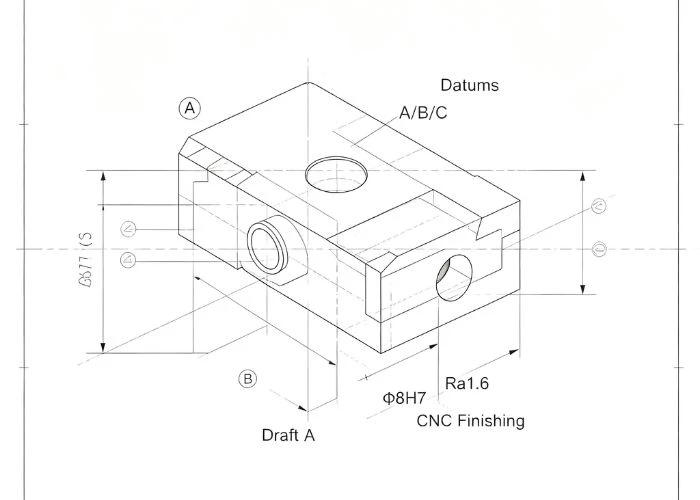
I usually begin by identifying the surfaces or features that physically locate the part. A mounting face may establish how a housing seats against a frame. A bore or locating boss may control lateral position. Another feature may prevent rotation. These relationships are more meaningful than selecting a cosmetic surface simply because it is visually prominent.
GD&T Basics similarly notes that, where possible, datum features should be selected in an order that reflects how the part assembles in real life, so the resulting reference frame represents part functionality. I consider this especially useful for plastic prototyping, where physical assembly often reveals which relationships actually control fit.
A Convenient Machining Surface Is Not Always the Best Design Datum
From a manufacturing perspective, some surfaces are easier to fixture, probe, or machine from than others. That does not automatically make them the best design datum. The design datum should communicate the functional reference required by the product, while manufacturing planning determines how that reference can be reproduced efficiently during machining.
If an easy-to-machine cosmetic surface has little relationship to the final locating interface, using it as the dominant design reference can make downstream geometric control less meaningful. In that case, I would rather understand which mounting, locating, or mating feature actually controls the finished part before deciding how the CNC setup should relate to it.
How Do Primary, Secondary, and Tertiary Datums Work Together?
Primary, secondary, and tertiary datums establish precedence within the reference system. I find this easier to understand through a real part rather than treating A, B, and C as abstract letters. A CNC-machined plastic housing provides a useful example because its mounting, locating, and orientation relationships are often easy to identify.
Suppose the bottom mounting surface is Datum Feature A because it establishes how the housing seats against another component. A locating bore is Datum Feature B because it establishes an important lateral reference. A side locating feature becomes Datum Feature C to complete the required orientation. Together, these references establish the framework for controlling other functional features.
This does not mean every part should use exactly this arrangement. If the product is located by two holes, a shaft, a slot, or another feature pattern, a different datum structure may better represent function. A pattern of holes can itself serve as a datum feature when that pattern performs the locating role in the assembly.
How Do Datums Affect CNC Machining Setup?
Datum information influences machining strategy, but I do not treat a drawing datum and a CNC machine work zero as the same concept. The drawing datum communicates design and inspection intent. The machine coordinate system is a manufacturing tool. My job is to establish a controlled relationship between them so the required geometry is actually produced.
For a simple part completed in one setup, this relationship may be straightforward. For a part that must be flipped or repositioned, I need to consider which physical features can reliably re-establish the required reference. A convenient fixture surface may be used during machining, provided the manufacturing plan still preserves the relationships required by the drawing.
This distinction is important in CNC plastic machining because I am not trying to make the machine coordinate system look identical to the drawing. I am trying to manufacture the specified features so that they satisfy the geometric relationships defined from the datum reference frame.
Datum Transfer Matters When a Part Requires Multiple Setups
When a part moves from one setup to another, the manufacturing reference must be transferred in a controlled way. A machined face, bore, locating feature, fixture interface, or other repeatable geometry may help establish the next setup. What matters is how accurately the new setup preserves the relationships required by the drawing.
If reference transfer is poorly planned, individual features can still look acceptable while relationships between features machined in different setups become less consistent. I therefore consider setup sequence early rather than waiting until the final inspection to discover that a cross-setup relationship is difficult to control.
How Are Datums Used During Part Inspection?
Inspection should evaluate a part from the reference system required by the drawing rather than from whichever surface is easiest to measure. Because a datum is theoretically exact, inspection uses physical or mathematical datum simulators to establish the reference from the actual datum features before evaluating controlled geometry.
A planar datum feature may be simulated by appropriate inspection equipment or mathematically fitted measurement data. A bore used as a datum feature may require a suitable simulator or measured cylindrical data to establish its derived axis. The exact method depends on the feature, drawing requirement, and inspection system.
The important principle is consistency. If the drawing defines a hole position relative to A | B | C, inspection should recreate that intended reference relationship as closely as the specified GD&T requires. Measuring the same hole from an unrelated convenient edge can produce a number, but that number may not answer the geometric question the drawing is asking.
What Happens When the Wrong Datum Is Selected?
A poor datum choice does not always produce an obviously oversized or undersized part. The more subtle risk is that inspection may confirm dimensions relative to a reference that does not represent the real functional interface. The part can then appear geometrically controlled on paper while the important mating or locating relationship remains insufficiently represented.
Consider a plastic housing whose internal connector must align with another component during assembly. If the connector position is controlled from a cosmetic outer surface that does not actually locate the housing, variation between that surface and the true mounting interface can weaken the connection between drawing acceptance and assembly performance.
A better approach is to identify the surfaces and features that establish the actual functional position first. The datum structure can then provide a common language for design, manufacturing, and inspection instead of creating an arbitrary coordinate system that exists mainly for drawing convenience.
More Datum References Do Not Automatically Create Better Control
I also avoid assuming that adding more datum references automatically improves a drawing. The datum reference frame should constrain the degrees of freedom necessary for the specified requirement and represent functional intent. Additional references that do not serve that purpose can make interpretation and inspection more complicated without improving the part.
The better question is not how many datum letters a drawing contains, but whether the selected datum features establish a stable and meaningful reference for the controlled geometry. I prefer a clear functional reference structure over unnecessary complexity.
How Should Datums Be Defined for Plastic Prototype Parts?
The same GD&T principles apply to plastic parts, but physical behavior can influence how practical a datum feature is to reproduce. When I review a plastic prototype, I consider not only whether a feature represents design intent, but also whether the actual manufactured feature can establish a sufficiently repeatable reference during machining and inspection.
A broad and stable mounting surface may provide a more repeatable physical reference than a very flexible wall that deflects easily under contact. Similarly, a functional locating bore may provide more meaningful information than a cosmetic contour that does not establish the product’s assembled position.
This does not mean flexible or complex plastic geometry can never be used in a datum system. It means the designer and manufacturer should understand how that datum will actually be established. A useful datum feature must represent functional intent while remaining physically meaningful enough for manufacturing and verification.
Should Surface Finishing Be Considered When Selecting a Datum?
Datum planning should also consider the condition in which the final requirement applies. In plastic prototyping, machining may be followed by sanding, painting, polishing, coating, printing, or other finishing operations. If a datum feature or a controlled interface is affected by these operations, the drawing should make the intended final condition clear.
For a functional locating or mating surface, I first consider whether the finish should be allowed to alter that interface. In some projects, functional areas are protected while cosmetic surfaces receive finishing. In others, the final finished surface is the condition that must be inspected. The correct decision depends on the product requirement rather than a universal rule.
For this reason, I treat surface finishing as part of the manufacturing condition when it can affect a datum or functional interface. This helps prevent a part from being accepted in one condition while its final assembled condition depends on another.
How We Review Datum GD&T Before CNC Plastic Machining
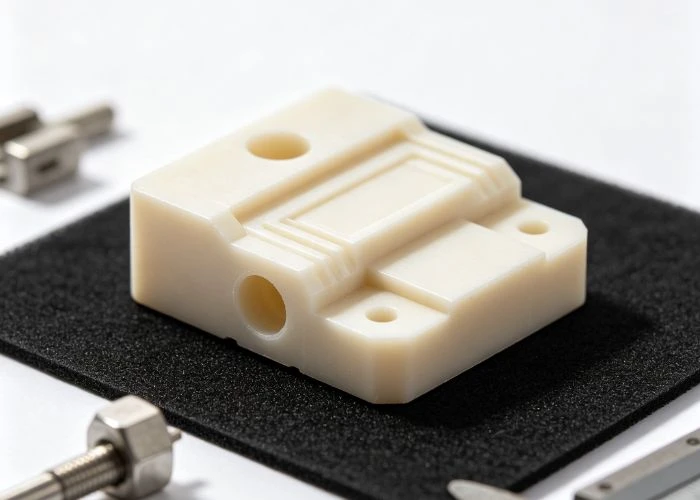
At UForProto, I review datum information as part of the engineering preparation for CNC plastic machining. As a direct plastic prototype manufacturer rather than a trading company, our goal is to understand how the drawing should translate into a manufacturable and inspectable plastic part before machining begins.
I review the 3D CAD together with the 2D drawing when both are available. For datum-related requirements, I pay particular attention to the designated datum features, datum precedence, critical feature relationships, machining access, setup requirements, and how the specified relationship can be verified after manufacturing.
I do not assume that a manufacturer should silently redesign the customer’s GD&T. If a datum relationship is ambiguous, conflicts with the apparent functional requirement, or is difficult to reproduce reliably during machining and inspection, I prefer to raise the issue before machining rather than guess the designer’s intent.
For plastic prototyping projects, engineers, R&D teams, and purchasing teams can send us their CAD files, 2D drawings, GD&T requirements, material specifications, quantities, and critical dimensions. This allows me to review both the part geometry and the manufacturing requirements before quotation and production planning.
Conclusion
A datum in GD&T should create a meaningful connection between design intent, manufacturing, inspection, and assembly. I select and interpret datum features by considering how the real part locates, which relationships matter functionally, and how those references can be reproduced during CNC machining and verification. A convenient surface is not automatically the right design datum, and a machine work zero is not automatically the drawing datum. For plastic prototype projects, customers can send UForProto CAD files, 2D drawings, GD&T requirements, materials, quantities, and critical dimensions for manufacturing review and quotation.
FAQs
1. What Is a Datum in GD&T?
A datum is a theoretically exact reference such as a plane, axis, line, or point used to establish geometric relationships on a part. It is derived from a physical datum feature and can become part of a datum reference frame used to evaluate location, orientation, profile, runout, and other applicable geometric requirements.
2. What Is the Difference Between a Datum and a Datum Feature?
A datum feature is the real physical surface or feature of size on the manufactured part. The datum is the theoretically exact reference derived from that feature. For example, a physical bore may be a datum feature, while its theoretically derived axis becomes the datum used by the geometric control.
3. How Do I Choose a Datum for a CNC Machined Part?
I start with how the part functions and locates in the real assembly. Mounting faces, locating holes, bosses, shafts, slots, and other mating features are often more meaningful candidates than arbitrary cosmetic surfaces. The selected datum features should communicate functional relationships while remaining practical to establish during manufacturing and inspection.
4. What Are Primary, Secondary, and Tertiary Datums?
They establish the precedence of references within a datum reference frame. The primary datum is established first, followed by the secondary and then tertiary datum. Each lower-precedence datum constrains the remaining degrees of freedom required by the geometric control after the higher-precedence references have been established.
5. Does a CNC Machine Datum Have to Match the Drawing Datum?
Not necessarily. A drawing datum defines the reference required by design and inspection, while the machine work coordinate system is established for manufacturing. I may use practical fixture or machining references, but the process must maintain a controlled relationship to the drawing datum system so the finished features satisfy the specified geometric requirements.
6. Why Are Datums Important for Part Inspection and Assembly?
Datums allow inspection to evaluate features from a reference system intended to represent the part’s functional relationships. When the datum structure reflects how the part actually locates in assembly, measured geometric results have a stronger connection to whether holes, surfaces, axes, and mating features will align as intended.