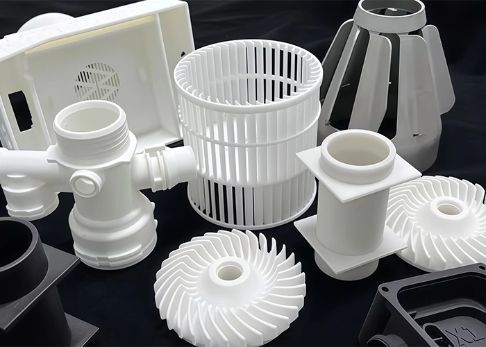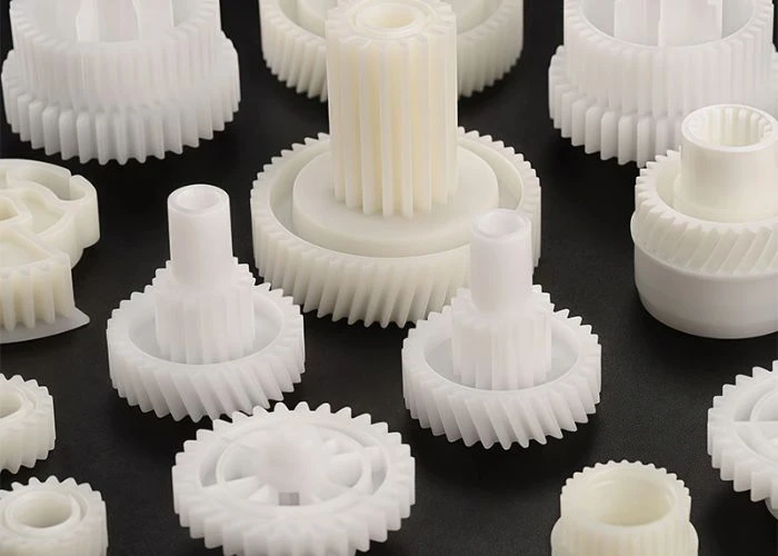

Plastic 3D printing allows us to turn CAD models into physical prototype parts without conventional tooling, making it valuable for fast design iteration, complex geometry, appearance evaluation, and selected functional checks. However, a successful printed prototype depends on much more than choosing a printer. Process, material, part orientation, geometry, surface requirements, post-processing, and the purpose of the prototype all influence the result. As a direct plastic prototype manufacturer, we use plastic 3D printing as one part of a broader plastic prototyping strategy rather than treating it as a universal replacement for other manufacturing processes.
What Is Plastic 3D Printing?
Plastic 3D printing is a group of additive manufacturing technologies used to build polymer parts directly from digital models. Instead of cutting material away from a solid block, the part is created progressively through controlled layers or repeated build steps. The important engineering point is that different plastic 3D printing technologies create very different material structures, surfaces, and mechanical behavior.
A CAD model is first converted into manufacturing data that the selected printing system can interpret. The machine then forms the geometry using resin, thermoplastic powder, filament, or another polymer-based material system. Because the geometry is created additively, designers can often manufacture internal features, curved forms, integrated structures, and shapes that would require difficult tool access with conventional machining.
This freedom makes plastic 3D printing especially useful during product development. Engineers can produce physical parts before committing to tooling and evaluate scale, ergonomics, interfaces, basic assembly relationships, surface appearance, and overall design intent while the CAD model is still changing.
However, we do not treat “3D printable” as the same thing as “appropriate for validation.” A printed housing intended only for visual review has different requirements from a structural bracket, snap-fit part, fluid-handling component, or prototype that must represent a specific engineering plastic.
That distinction is important because plastic prototyping should answer a development question. We therefore start by understanding what the customer wants to learn from the part before deciding whether plastic 3D printing is the right manufacturing route.
How Does Plastic 3D Printing Turn CAD Into a Physical Prototype?
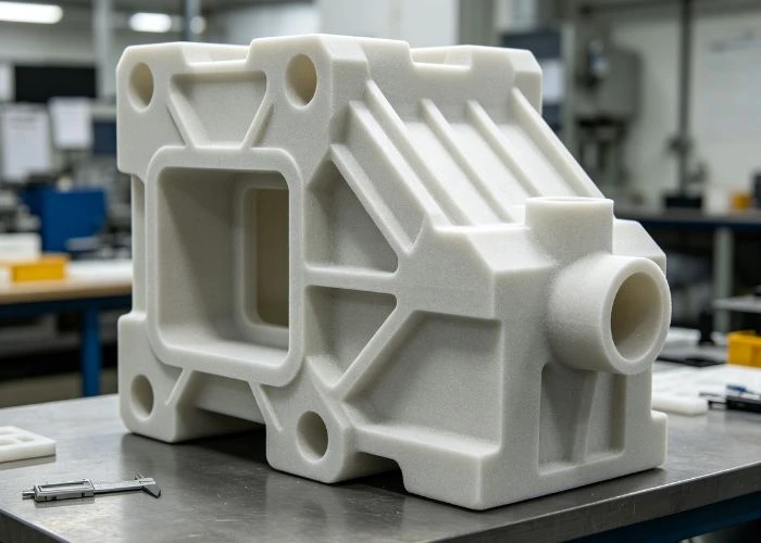
The plastic 3D printing workflow begins well before material is built. CAD preparation, orientation, feature review, process selection, printing, and post-processing all influence the usable prototype. When engineers understand these stages as one manufacturing chain, it becomes easier to explain why two parts printed from the same CAD file can still perform differently.
From CAD Geometry to a Printable Build
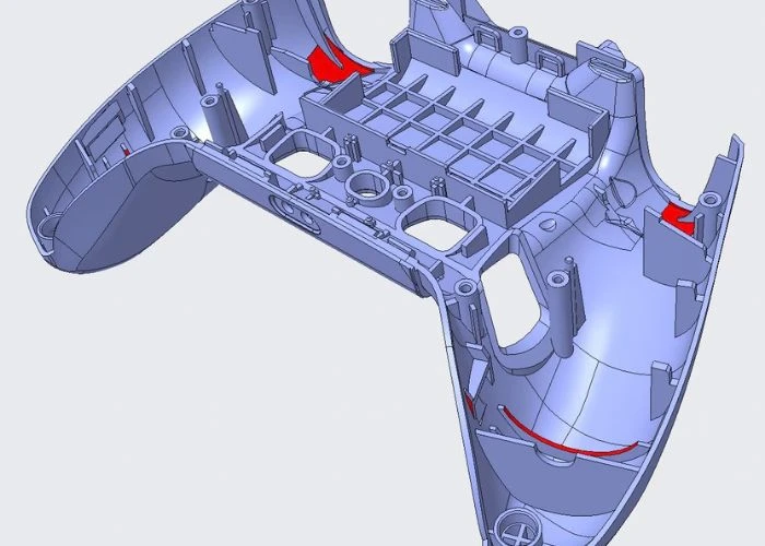
Before printing, we review the CAD model in relation to the selected process rather than treating the file as automatically ready for production. Wall thickness, thin ribs, narrow gaps, enclosed cavities, internal channels, small holes, text, unsupported features, and critical mating areas can all affect how the part should be prepared.
Build orientation is particularly important. Changing the orientation can alter support requirements, surface condition, layer relationships, build height, post-processing effort, and sometimes the mechanical response of the part. The best orientation for manufacturing speed may therefore not be the best orientation for a visible cosmetic surface or a critical interface.
For SLA, we also need to consider where supports contact the part and whether those areas will remain visible after finishing. For powder-based SLS, support structures are generally unnecessary because surrounding powder supports the geometry, but enclosed cavities still require a practical way to remove residual powder.
This is why our review starts from the final prototype requirement. We want to understand which areas remain visible, which dimensions interact with another component, where surface quality matters, and how the customer will handle or assemble the part after delivery.
Post-Processing Is Part of Plastic 3D Printing Quality
A printed part is not always a finished prototype when the machine stops. SLA parts normally require resin removal and controlled post-curing, followed by support removal and surface preparation where necessary. SLS parts require powder removal, and their naturally textured surface may remain acceptable for engineering evaluation or receive further finishing for presentation.
Post-processing can change more than appearance. Sanding affects edges and local dimensions, coatings add material, support remova
l can alter delicate features, and aggressive finishing can soften definition around fine geometry. If a painted prototype must assemble with another part, we therefore need to know which surfaces are functional and which are cosmetic before finishing begins.
This is particularly important for appearance prototypes. The customer may not only be evaluating printed geometry but also color, gloss level, texture, graphic position, gap appearance, and the relationship between several finished components.
Current industrial suppliers similarly treat post-processing as part of additive manufacturing rather than an unrelated cosmetic operation; finishing may be used to reduce roughness, add color, improve transparency, or modify the final surface condition.
Which Plastic 3D Printing Processes Matter Most for Prototype Development?
Plastic 3D printing includes several technologies, but they should not be treated as interchangeable machines that produce the same result. SLA, SLS, FDM, and other industrial processes use different material forms and build mechanisms, so their surface quality, material behavior, geometric freedom, and prototype applications can differ substantially.
Comparison Table
| Process | Material System | Surface / Detail | Support Requirement | Typical Prototype Value | UForProto |
| SLA | Photopolymer resin | Excellent detail and smooth surface | Supports required | Appearance models, detailed housings, visual evaluation | Supported |
| SLS | Thermoplastic powder, commonly PA/Nylon | Textured but consistent | No conventional supports | Functional geometry, clips, brackets, durable prototypes | Supported |
| FDM | Thermoplastic filament | Layer lines more visible | Process-dependent supports | Concept models, general-purpose prototypes | Industry reference only |
| MJF | Thermoplastic powder | Fine, uniform powder-bed finish | No conventional supports | Functional plastic parts and batch production | Industry reference only |
The table is a practical overview rather than an absolute ranking. Machine type, material grade, part orientation, wall thickness, geometry, parameter control, and post-processing can change the actual result. Protolabs also distinguishes SLA as a process suited to smooth cosmetic parts and fine detail, while SLS thermoplastic parts are commonly used for durable prototyping and functional applications.
SLA Works Best When Detail and Appearance Drive the Prototype
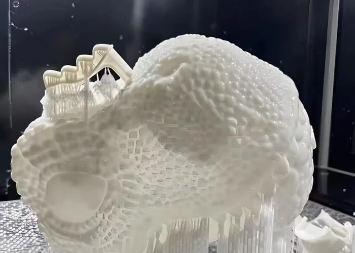
Stereolithography uses controlled light to selectively cure liquid photopolymer resin. For prototype projects, its biggest advantage is usually the combination of fine detail, smooth surfaces, relatively sharp edge definition, and the ability to create visually refined geometry.
We often consider SLA for product housings, presentation models, ergonomic shapes, design-review parts, small detailed components, transparent or translucent concepts, and prototypes that will later be painted or otherwise cosmetically finished.
However, engineers should distinguish an SLA resin from the conventional thermoplastic that a final production product may use. A resin described as “ABS-like” can approximate selected ABS characteristics, but that does not make it chemically identical to standard ABS sheet, block, or molded ABS.
This distinction matters when the purpose moves from visual evaluation to material-specific functional testing. A resin can provide enough performance for many prototype checks while still being inappropriate if the test depends on the actual creep, fatigue, chemical resistance, thermal expansion, or long-term behavior of the final polymer.
For that reason, we use SLA where its geometry and surface advantages support the development objective rather than assuming it should represent every production plastic.
SLS Adds Value When Geometry and Functional Handling Matter
Selective laser sintering fuses thermoplastic powder into solid geometry. Nylon-based materials are widely associated with SLS, and the surrounding powder supports the part during the build. This eliminates many of the dedicated support structures required by resin or filament processes and gives designers greater freedom around complex shapes.
We often evaluate SLS for brackets, clips, snap-fit concepts, ducts, protective structures, internal mechanical parts, complicated housings, and geometry that would otherwise need multiple supports or difficult tool access.
The surface is normally more textured than SLA, so SLS is not automatically the first choice when the customer wants a smooth cosmetic housing directly from the printer. Its value is more often found in geometry freedom, durable handling, thermoplastic material behavior, and practical functional evaluation.
SLS can also simplify the production of several different parts in the same build because multiple geometries can be arranged within a powder-bed build volume. That can be useful when a prototype assembly contains many small components and the engineering team wants to review their relationship together.
At UForProto, this makes SLS an important complement to SLA rather than a competing version of the same process.
How Should Engineers Think About Plastic 3D Printing Materials?
Material selection is one of the most misunderstood parts of plastic 3D printing. Familiar names such as ABS, PC, PP, nylon, or “engineering resin” can create the impression that printed materials directly reproduce conventional plastics. In practice, we evaluate the material system together with the printing process because both determine what the prototype can realistically validate.
Resin Names Should Not Be Confused With Production Plastic Names
SLA uses photopolymer resin rather than conventional melt-processed thermoplastic stock. Resin manufacturers can formulate materials to emphasize rigidity, toughness, transparency, temperature capability, flexibility, or other useful properties.
This gives engineers a large design space, but it also requires careful language. An ABS-like resin may reproduce selected stiffness or impact characteristics associated with ABS, while a transparent resin may provide useful optical appearance without behaving like machined PMMA or PC in every engineering condition.
For visual prototypes this difference may not matter. If the objective is to confirm a housing shape, button position, display opening, overall appearance, or ergonomic form, the material only needs to provide the properties necessary for that evaluation.
If the test depends on the exact production plastic, however, we review the requirement differently. In that situation, CNC plastic machining from real engineering-plastic stock may provide more representative material behavior.
This boundary is one reason plastic 3D printing and CNC plastic machining work well together in prototype development rather than replacing each other.
Powder-Based Thermoplastics Provide a Different Validation Route
SLS commonly uses thermoplastic powders such as PA11 and PA12 families. These materials can provide a useful combination of durability, flexibility, and complex geometry, making them valuable for engineering prototypes that will be repeatedly assembled, handled, clipped, or evaluated.
The same material family can still include different grades, fillers, modifiers, and performance levels. Engineers therefore should not stop at a generic description such as “nylon.” The exact grade and the required prototype behavior remain important.
Industrial plastic 3D printing has also expanded beyond nylon. Powder-bed processes may support polypropylene, TPU, reinforced polyamides, and other materials depending on the equipment. HP, for example, currently lists PA, PP, and elastomer systems within its polymer additive-manufacturing portfolio.
For UForProto projects, however, we do not expand the service scope simply because another material exists somewhere in the additive-manufacturing market. We review the materials that we can actually manufacture through our SLA and SLS capabilities and recommend another prototype process when the required validation cannot be represented reliably.
What Engineering Advantages and Limitations Does Plastic 3D Printing Have?
The value of plastic 3D printing comes from solving particular development problems quickly, not from being universally faster or cheaper than every alternative. Its strongest advantages normally appear when geometry is still changing, quantities are low, and engineers need physical feedback before committing to more restrictive manufacturing decisions.
Plastic 3D Printing Creates Value Through Iteration and Geometry
The absence of conventional mold tooling allows CAD changes to move into another physical iteration with relatively little manufacturing rework. Engineers can compare multiple housing concepts, ergonomic shapes, interface positions, internal layouts, or mechanical ideas while the design is still evolving.
Additive construction also removes some tool-access restrictions associated with subtractive manufacturing. Internal passages, curved channels, enclosed geometry, integrated brackets, organic surfaces, and consolidated structures may be significantly easier to create through plastic 3D printing.
This can reduce the temptation to modify the design purely because a cutting tool cannot reach a feature. During early plastic prototyping, that freedom helps teams evaluate product intent before manufacturing constraints become the dominant concern.
Small quantities are another natural fit. When only one or several parts are needed for development, the lack of dedicated production tooling can make the first physical iteration faster and more practical.
The real benefit is not simply “printing quickly.” It is shortening the time between an engineering question, a CAD change, a physical part, and the next informed design decision.
A Printed Prototype Can Give the Wrong Answer if the Validation Goal Is Wrong
Plastic 3D printing has limitations precisely because the printed part is created through a particular additive process. Layer relationship, curing, powder fusion, surface condition, material formulation, orientation, and post-processing can all influence performance.
A prototype can therefore look convincing while still being unsuitable for the test being performed. For example, a visually excellent SLA housing may confirm appearance and assembly access but may not reproduce the long-term impact, thermal behavior, or chemical exposure performance of a final molded engineering plastic.
Dimensional expectations need similar care. Printer specifications may describe machine capability, but real prototype accuracy also depends on part size, orientation, support, wall thickness, geometry, material, finishing, and measurement conditions.
Surface quality also differs by process. SLA can create smoother visual surfaces, while SLS normally carries a more textured powder-bed finish. A customer-facing cosmetic model may therefore require sanding, priming, painting, or other finishing even when the underlying geometry is correct.
The correct question is not whether plastic 3D printing is “accurate enough” in general. We ask whether the complete printed and finished part is suitable for the specific engineering decision the customer intends to make.
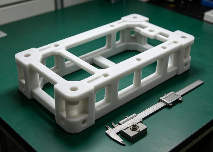
Where Does Plastic 3D Printing Add the Most Value in Plastic Prototyping?
We see the strongest value when plastic 3D printing is matched to the type of feedback the development team needs. A single product may use SLA, SLS, CNC plastic machining, or another prototype route at different stages because appearance, assembly, material behavior, and manufacturing questions do not all need to be answered by the same part.
Early Design and Appearance Validation
During early development, engineers often need to understand whether the digital design works physically before they need final-material performance. Plastic 3D printing can quickly make the CAD model tangible so teams can review scale, ergonomics, grip, visual balance, component space, openings, button positions, display relationships, and overall product architecture.
SLA becomes particularly useful where the development team cares about visual detail. After appropriate sanding and surface finishing, a printed housing can support design reviews, presentation models, internal approval, customer evaluation, and CMF-related discussions.
This does not mean the part needs to imitate final production in every technical property. Its job may simply be to reveal whether the product looks, feels, and integrates the way the team expected from the digital model.
That distinction helps prevent unnecessary cost. Using production-equivalent materials and extremely tight specifications for an early appearance question may provide little additional engineering value.
Functional Geometry and Assembly Evaluation
Plastic 3D printing also supports functional development when the test depends primarily on geometry rather than exact production-material behavior. Engineers may need to check whether a bracket clears neighboring components, whether a snap feature can engage, whether cable space is sufficient, or whether several parts can be assembled in the intended sequence.
SLS can be particularly useful for this type of work because its powder-supported build allows complicated structures and nylon parts without conventional support removal inside many geometries.
Multi-part builds also benefit from coordination. The value of a printed component is often not fully understood until it is brought together with the surrounding prototype. We therefore consider mating parts, fastening positions, visible surfaces, and customer-supplied components when the printed geometry belongs to a larger assembly.
UForProto already uses this broader approach across prototype projects: different components may follow CNC plastic machining, SLA/SLS 3D printing, vacuum casting, finishing, and assembly routes according to what the final build requires, rather than forcing every part into one process.
How Do We Decide Whether a Real Project Should Use Plastic 3D Printing?
For a real RFQ, we do not make the decision from process names alone. We review what the prototype must demonstrate, which material behavior matters, which interfaces require control, what surface condition is expected, how many parts are needed, and whether the components will later be finished or assembled. That context determines whether printing actually reduces development risk.
The Prototype Goal Should Drive the Manufacturing Route
If the customer mainly needs to review geometry, shape, appearance, ergonomic relationships, or several rapid design iterations, plastic 3D printing is often an efficient starting point. SLA may be appropriate where surface and detail dominate, while SLS may be stronger when complex geometry and durable handling are more important.
If several printed parts later need to become a finished assembly, we also review surface finishing, visible areas, mating relationships, and supplied components before manufacturing. This avoids making a part successfully and discovering afterward that its finish or assembly requirement should have changed the printing plan.
Quantity is another consideration, but it should not be treated as the only decision rule. A very complex single component may favor plastic 3D printing, while a simple geometry made from a required engineering plastic may be better suited to CNC even at the same quantity.
For this reason, our engineering review combines geometry, validation purpose, material, finish, assembly scope, and quantity instead of relying on a fixed rule such as “early stage equals 3D printing.”
When CNC Plastic Machining Becomes the Better Prototype Route
CNC plastic machining becomes more attractive when the engineering team needs the prototype directly from a specific solid engineering plastic. ABS, PMMA, PC, PP, POM, PA, PPS, PE, and other stock plastics can provide material behavior that a printed substitute may not represent closely enough.
Critical machined interfaces can also change the process decision. Bearing seats, machined mating surfaces, threaded features, precision openings, datum relationships, or other controlled features may make subtractive manufacturing more appropriate when they dominate prototype performance.
This does not mean CNC is inherently “better” than plastic 3D printing. It means the two processes answer different questions. The existing UForProto medical-device content already follows this boundary by using 3D printing for rapid design development and CNC where production-grade plastics and more demanding functional validation become important.
We therefore avoid selecting a process based on technology preference. The better route is the one that gives the engineering team the most reliable evidence for the next design or purchasing decision.
How We Support Plastic 3D Printing Projects at UForProto
Plastic 3D printing becomes more useful when printing, finishing, inspection, and assembly are considered as connected manufacturing stages. As a direct plastic prototype manufacturer rather than a trading company, we review the customer’s CAD data and prototype objective first, then organize SLA, SLS, CNC plastic machining, finishing, or assembly around the required result.
We support SLA for detailed and appearance-focused prototype parts and SLS for nylon-based functional geometry. Where printed material cannot provide the required engineering evidence, we can evaluate CNC plastic machining using real engineering-plastic stock instead of forcing the project to stay with additive manufacturing.
For customer-facing prototypes, our work can continue beyond raw printing into hand finishing and surface treatment. Depending on the design requirement, that may include sanding, painting, silk screening, UV-related finishing, or other suitable cosmetic work before components move into final prototype assembly.
Multi-part products can also combine manufacturing routes. One housing may be SLA printed for appearance, an internal bracket may use SLS, and another precision component may be CNC machined. The parts can then return to a coordinated finishing and assembly stage rather than being treated as unrelated orders.
This combined approach is already part of how UForProto handles prototype manufacturing, with projects involving CNC plastic machining, SLA/SLS 3D printing, vacuum casting, surface finishing, and prototype assembly according to the required deliverable.
Engineers, R&D teams, industrial designers, and purchasing teams can send us 3D CAD files together with quantity, material expectations, critical dimensions, surface requirements, intended prototype use, and assembly information. These details help us determine whether SLA, SLS, CNC plastic machining, or a combined plastic prototyping route is the most practical manufacturing solution.
Conclusion
Plastic 3D printing is most valuable when the process is matched to the question a prototype must answer. SLA can provide refined detail and appearance, while SLS offers greater freedom for complex nylon geometry and functional handling. Material choice, orientation, post-processing, surface requirements, and assembly context all influence whether the printed part produces useful engineering evidence. When actual engineering-plastic behavior or critical machined features become more important, CNC plastic machining may be the better route. As a direct plastic prototype manufacturer, UForProto can review your CAD files, drawings, quantities, materials, finishing requirements, and assembly scope and provide a practical prototype manufacturing quotation.
FAQs
1. What Is Plastic 3D Printing?
Plastic 3D printing is additive manufacturing that creates polymer components directly from digital 3D models. Different processes use materials such as photopolymer resin, thermoplastic powder, or filament. The process is widely used in plastic prototyping because it can create physical parts without conventional molds and can support rapid design changes, complex geometry, appearance evaluation, and selected functional validation.
2. Which Plastic 3D Printing Process Is Best for Prototype Parts?
There is no universal best process. SLA is often appropriate when smooth surfaces, fine detail, visual presentation, or transparent concepts matter. SLS is often useful when engineers need complex nylon geometry, durable handling, clips, brackets, or functional structures. The correct process should be selected according to the prototype’s validation objective, geometry, material behavior, finish, and assembly requirements.
3. What Materials Are Commonly Used in Plastic 3D Printing?
Material depends on the technology. SLA uses photopolymer resins formulated for properties such as rigidity, toughness, clarity, flexibility, or heat resistance. SLS commonly uses thermoplastic powders such as PA11 or PA12 nylon families. Other industrial technologies can process PP, TPU, reinforced polyamides, and additional polymers. Engineers should always evaluate the actual grade rather than relying only on a generic material name.
4. Is Plastic 3D Printing Suitable for Functional Prototypes?
Yes, when the functional test depends on geometry or on properties that the selected printing material can represent adequately. SLS nylon can be useful for clips, brackets, assembly concepts, and repeatedly handled components, while engineering SLA resins can support selected functional checks. If the test depends strongly on the exact behavior of a production-grade plastic, machining the prototype from actual stock material may provide more reliable evidence.
5. Does Plastic 3D Printing Require Surface Finishing?
It depends on the prototype. Raw SLS parts may be perfectly acceptable for engineering evaluation, while an SLA housing intended for customer presentation may require support removal, sanding, priming, painting, or graphics. Surface finishing should be considered before manufacturing because finishing can change appearance, edges, local dimensions, and mating conditions.
6. When Should I Use CNC Plastic Machining Instead of Plastic 3D Printing?
CNC plastic machining is often more suitable when the prototype must use a specific production-grade engineering plastic, when critical machined interfaces need closer control, or when the validation depends on material behavior that a printed substitute cannot represent adequately. Plastic 3D printing is usually stronger for rapid iteration and complex geometry; CNC becomes more valuable when actual stock material and controlled machined features are the priority.