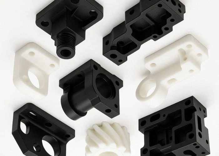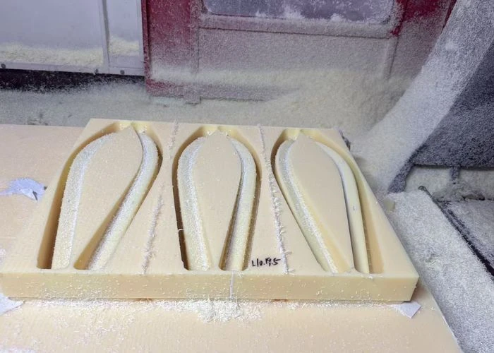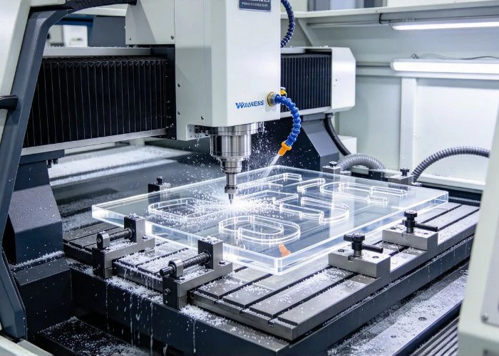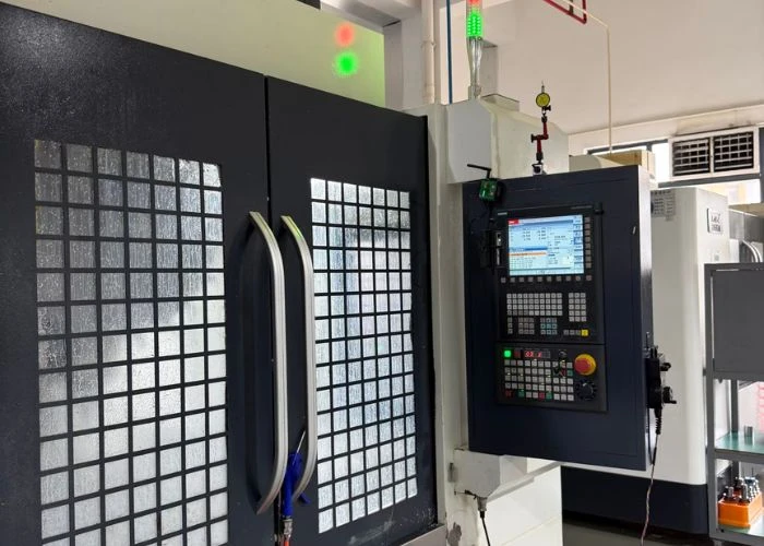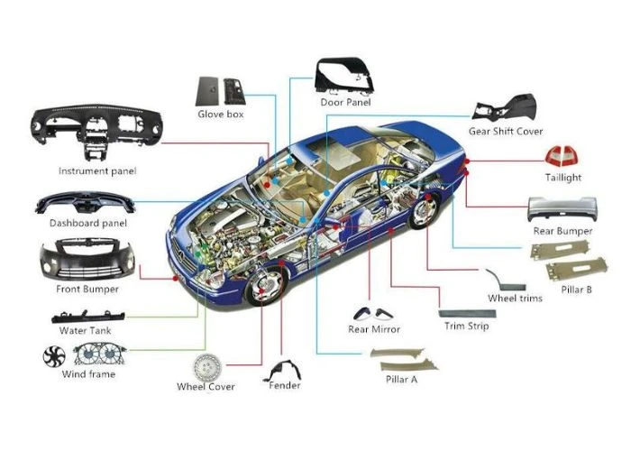

PVC CNC machining is an effective method for producing rigid plastic prototypes, but maintaining dimensional accuracy requires careful control of heat, material stress, and cutting conditions. Poor workholding or unsuitable part geometry can lead to warping, burrs, and inconsistent tolerances. In plastic prototyping, these problems may affect assembly fit and functional performance. By understanding PVC material behavior and applying practical machining and design strategies, engineers can improve part quality, reduce manufacturing risks, and develop more reliable prototypes.
What Makes Rigid PVC Suitable for CNC Machining?
Rigid polyvinyl chloride (PVC-U or uPVC) is commonly selected for components requiring chemical resistance, electrical insulation, and structural rigidity. In PVC CNC machining, rigid sheets and rods can be milled, drilled, or turned into custom geometries without expensive molds. However, engineers must consider the material’s temperature sensitivity, mechanical behavior, and dimensional stability before choosing it for precision plastic prototypes.
Unlike flexible PVC, rigid PVC contains little or no added plasticizer, allowing it to maintain greater stiffness under normal operating conditions. This makes it suitable for certain industrial equipment components, electrical insulating supports, chemical-resistant fixtures, and fluid-handling parts.
One important advantage of PVC is its resistance to many acids, alkalis, and aqueous chemical solutions. However, chemical compatibility depends on concentration, temperature, exposure duration, and the specific PVC formulation. We recommend reviewing supplier material data before selecting PVC for chemically demanding applications.
PVC also has limitations. Its relatively low thermal conductivity and restricted service-temperature range can create difficulties during machining and application. Although rigid PVC is generally machinable, it may experience local softening, surface damage, or dimensional changes if cutting conditions are poorly controlled.
For this reason, we evaluate PVC according to the component’s intended environment, mechanical loads, geometric complexity, and required tolerances rather than selecting it solely for its material properties.
What Are the Main Challenges in PVC CNC Machining?
PVC CNC machining can produce accurate components, but several material-related challenges must be managed throughout the manufacturing process. Heat accumulation, residual stress, clamping deformation, and poor chip formation may affect both surface quality and dimensional accuracy. We focus on understanding the causes of these problems because adjusting cutting parameters alone cannot always correct defects associated with material behavior or part design.
Heat Buildup and Surface Damage
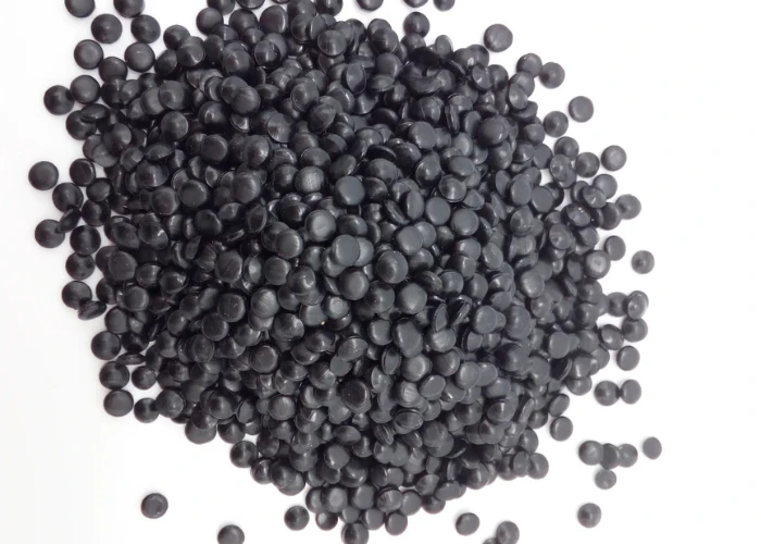
Heat generation is a major concern when machining rigid PVC. Because PVC has relatively low thermal conductivity, heat generated near the cutting edge may accumulate locally instead of dissipating quickly through the workpiece. This becomes more problematic when tools are dull or cutting conditions encourage rubbing rather than efficient material removal.
Excessive heat may cause softened edges, smeared surfaces, discoloration, or dimensional instability. At sufficiently high temperatures, PVC can also undergo thermal degradation and release hazardous decomposition products, including hydrogen chloride. Therefore, thermal control is both a machining-quality requirement and an important workplace safety consideration.
We recommend using sharp cutting tools, maintaining effective chip evacuation, and selecting cutting parameters that produce clean chips without excessive friction. Increasing spindle speed is not always beneficial because cutting speed, feed per tooth, and tool geometry must be balanced.
The plastic machining guidelines from Curbell Plastics also emphasize sharp cutting tools, effective chip removal, and temperature control when machining thermoplastics.
For engineers working with other thermoplastics, similar thermal-control principles are discussed in our article on plastic melting during CNC machining.
Warping and Clamping Deformation
Warping often occurs when internal stresses are redistributed during machining. Removing a large amount of material from one side of a PVC plate can disturb the stress balance within the stock, causing the component to bend or twist after machining.
Clamping pressure can introduce additional distortion. A thin PVC component may remain flat while secured in a fixture but change shape after the clamps are released. As a result, dimensions measured during machining may differ from the final free-state geometry.
We recommend using balanced material-removal strategies, distributing clamping forces evenly, and maintaining sufficient support beneath flexible sections. For parts requiring substantial material removal, staged roughing and finishing may help reduce deformation.
Burrs, Edge Chipping, and Surface Finish Problems
Burrs commonly develop around drilled holes, milled slots, and unsupported edges. Their formation depends on tool sharpness, feed conditions, cutting direction, and the amount of support surrounding the feature. Poor cutting conditions may also produce rough surfaces or irregular edge geometry.
Rigid PVC can also experience edge chipping when cutting forces act on thin or poorly supported sections. This is particularly important for cosmetic prototypes, sealing surfaces, and components requiring accurate assembly.
We recommend supporting vulnerable edges, selecting appropriate cutting directions, and minimizing unnecessary secondary finishing. Although manual deburring can improve appearance, excessive material removal during finishing may alter critical dimensions.
How Can Engineers Control Tolerances in PVC CNC Machining?
Tolerance control is essential when CNC-machined PVC components must fit accurately with other parts. Although modern CNC machines offer precise positioning, final part accuracy also depends on thermal expansion, material stress, clamping conditions, and inspection methods. We recommend evaluating these factors together before specifying tight tolerances, particularly for large components, thin-walled structures, and precision assembly features.
Thermal Expansion and Dimensional Stability
PVC expands and contracts as temperature changes. This behavior can affect dimensional measurements when components are machined or inspected at different temperatures. Even relatively small temperature differences may become important for large parts or components with tight assembly requirements.
For example, consider a 200 mm PVC component with an assumed linear thermal expansion coefficient of 70 × 10⁻⁶/K. If its temperature increases by 10°C, the theoretical dimensional change is approximately 0.14 mm.
This calculation is an illustrative example rather than a guaranteed value for every PVC grade. Actual thermal expansion depends on the material formulation and supplier specifications.
We recommend allowing machined components to reach a stable temperature before final inspection and defining reference conditions for critical dimensions. Engineers can also review our guide to dimensionally stable plastics when evaluating materials for precision applications.
Setting Realistic Tolerances for Critical Features
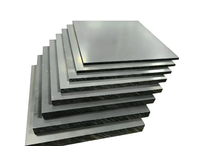
Not every dimension on a PVC prototype requires the same level of precision. Applying excessively tight tolerances to noncritical features can increase machining time, inspection costs, and manufacturing complexity without improving functional performance.
We recommend identifying critical dimensions such as mounting holes, locating surfaces, sealing interfaces, and mating features. These areas often require tighter dimensional control because they directly affect assembly alignment and component performance.
By comparison, external surfaces that do not influence fit or function may allow wider tolerances. For example, a PVC equipment cover may require accurate mounting-hole positions while permitting greater variation in its overall external dimensions.
We also distinguish dimensional tolerances from geometric tolerances. A component may satisfy individual length measurements while failing flatness, perpendicularity, or positional requirements. Appropriate datum references and geometric controls are therefore important for precision assemblies.
A universal tolerance such as ±0.05 mm should not be assumed achievable for every PVC part. The actual capability depends on material grade, part size, feature geometry, machining conditions, and measurement methods.
Inspection After Machining and Stress Release
Inspection should confirm the geometry of the finished component under conditions that represent its intended use. Measuring a PVC part immediately after machining may produce different results from measuring it after temperature stabilization.
Clamping conditions must also be considered. Thin components may appear dimensionally accurate while restrained but deform after removal from the fixture. We therefore recommend checking critical dimensions after unclamping whenever practical.
For parts involving significant material removal, rough machining followed by a stabilization period and final finishing may improve dimensional consistency. Any thermal stress-relief treatment must be validated against the specific PVC grade to avoid material damage.
The inspection method should match the tolerance requirement. Simple dimensions may be measured with calipers or micrometers, while complex profiles and positional features may require coordinate measuring machines or optical inspection systems.
Which Machining Practices Improve PVC Part Accuracy?
Accurate PVC CNC machining requires a coordinated approach to tool selection, cutting parameters, chip evacuation, and workholding. A machining strategy that performs well on a thick PVC block may not be suitable for a thin-walled component or large panel. We evaluate each operation according to the material grade, part geometry, and required surface quality rather than applying identical settings to every component.
Sharp cutting tools with suitable rake geometry help remove PVC efficiently while reducing friction. High-speed steel and carbide tools can both be suitable, depending on the operation, tool diameter, and required finish. Proper flute clearance also helps prevent chips from accumulating near the cutting edge.
Cutting speed and feed rate must be balanced. Excessively low feed relative to spindle speed may increase rubbing, while aggressive cutting conditions can create excessive forces and damage unsupported features. We recommend selecting parameters based on actual cutting behavior rather than relying on fixed RPM values.
Effective chip evacuation is equally important. Accumulated chips can be repeatedly cut, increasing local heat and damaging finished surfaces. Appropriate airflow or compatible chip-removal methods may help maintain stable cutting conditions, provided workplace safety requirements are met.
Workholding should support the component without introducing excessive distortion. For thin plates, distributed support may be more effective than concentrated clamping forces. Machining sequences should also preserve rigidity until critical features are completed.
In CNC plastic machining, these decisions are closely connected with design for manufacturability. Engineers can explore additional principles in our DFM guide before finalizing a prototype design.
How Should Engineers Design PVC Parts for CNC Machining?
Good design can prevent many PVC machining problems before manufacturing begins. Wall thickness, pocket depth, internal corners, hole placement, and assembly features all influence cutting stability and dimensional accuracy. We encourage engineers to consider these factors during CAD development because correcting unsuitable geometry after machining is often more expensive and time-consuming than improving the original design.
Wall Thickness, Pockets, and Internal Corners
Thin walls are sensitive to cutting forces and clamping pressure. When a wall lacks sufficient support, it may deflect during machining and return toward its original position after the tool passes, producing inconsistent thickness or surface quality.
We recommend evaluating wall thickness together with wall height, unsupported length, and material rigidity. A short wall supported on multiple sides may be easier to machine than a tall, unsupported wall of the same thickness.
Deep pockets can create additional challenges because long cutting tools are more susceptible to deflection and vibration. Where possible, reducing unnecessary pocket depth or improving tool access can increase machining stability.
Internal corners should also accommodate practical cutting-tool diameters. Since rotating end mills cannot produce perfectly sharp internal corners, adding suitable radii can reduce machining complexity and improve surface consistency.
For features requiring square mating geometry, we may consider corner reliefs or alternative machining methods. The objective is to preserve functional requirements without introducing unnecessary manufacturing difficulty.
Holes, Threads, and Assembly Features
Hole placement affects both machining stability and assembly accuracy. Holes positioned too close to edges or thin sections may weaken the surrounding material and increase the risk of breakout or deformation during drilling.
We recommend providing adequate edge distance, supporting hole exits where practical, and defining positional tolerances for critical mounting features. Hole locations should be evaluated in relation to the complete assembly rather than independently.
Rigid PVC can be machined with internal threads, but thread durability depends on material grade, engagement length, fastening load, and assembly frequency. Repeated tightening may damage plastic threads if the design is not appropriate.
For applications requiring frequent disassembly, we may evaluate compatible threaded inserts or alternative fastening arrangements. Insert installation methods must be selected carefully to avoid excessive stress or cracking around the mounting area.
Assembly clearances should also reflect realistic manufacturing variation. Components designed with zero nominal clearance may experience interference even when individual dimensions appear acceptable.
We recommend reviewing tolerance stack-ups across mating components to reduce alignment problems and unnecessary manual fitting during prototype assembly.
Before releasing a PVC design for manufacturing, engineers should confirm the material grade, critical tolerances, wall thickness, hole positions, tool accessibility, and surface requirements. Our plastic prototype build checklist provides additional guidance for preparing prototype manufacturing files.
When Should Engineers Choose PVC Over Other CNC Plastics?
PVC is not the ideal material for every plastic prototype. Although rigid PVC offers useful chemical resistance, electrical insulation, and structural rigidity, other engineering plastics may provide better impact strength, wear resistance, or temperature performance. We recommend selecting materials according to actual operating requirements rather than assuming that one plastic offers the best combination of properties for all applications.
Rigid PVC may be suitable for chemical-resistant fixtures, electrical insulating components, and certain industrial equipment parts. However, its suitability depends on chemical exposure, temperature, loading conditions, and required service life.
ABS may be preferable when impact resistance and general-purpose housing performance are important. POM is often considered for moving components because of its low friction and good wear characteristics.
PP can provide excellent resistance to many chemicals and offers low weight, but its lower stiffness and relatively high thermal expansion may create challenges for precision machining.
When choosing between PVC, ABS, PP, and POM, we recommend prioritizing the component’s operating environment, mechanical function, dimensional requirements, and manufacturing feasibility. Material selection should support the finished prototype’s performance rather than focus only on raw material cost.
What Should Engineers Check Before Ordering CNC-Machined PVC Prototypes?
Before requesting a quotation, engineers should provide sufficient technical information to evaluate machining feasibility, material suitability, and inspection requirements. In plastic prototyping, incomplete drawings or unclear tolerances can create manufacturing uncertainty and increase the likelihood of design revisions. We recommend preparing a complete technical package so potential problems can be identified before machining begins.
A 3D CAD model should be accompanied by a 2D engineering drawing identifying critical dimensions, geometric tolerances, and surface requirements. These documents help manufacturers understand which features are essential for assembly and functional performance.
Material specifications should identify the required rigid PVC grade, stock form, and relevant performance requirements. If the component will contact chemicals or operate under elevated temperatures, these conditions should be communicated during material selection.
Engineers should also clarify mounting interfaces, threaded connections, sealing surfaces, cosmetic expectations, and inspection requirements. These details influence machining strategy, finishing operations, and quotation accuracy.
As a China-based direct plastic prototype manufacturer, UForProto provides CNC plastic machining, 3D printing, vacuum casting, surface finishing, and prototype assembly services. We support engineering teams in reviewing plastic component designs and evaluating suitable manufacturing approaches.
For PVC-specific projects, material availability and processing suitability should be confirmed during technical review. Providing complete drawings and application requirements allows us to assess potential manufacturing challenges before accepting a project.
Conclusion
PVC CNC machining requires careful control of cutting heat, material stress, workholding, and dimensional stability to achieve consistent part quality. Common defects such as warping, burrs, and surface damage can often be reduced through suitable cutting conditions and machining sequences.
For engineers, defining realistic tolerances and optimizing wall thickness, holes, and assembly features are equally important. Material selection should also reflect the component’s mechanical, chemical, and temperature requirements.
By combining appropriate material selection, practical DFM principles, and reliable inspection methods, engineers can reduce manufacturing risks and improve the accuracy and performance of CNC-machined PVC prototypes.
FAQs
1. Is Rigid PVC Easy to CNC Machine?
Rigid PVC is generally suitable for CNC milling, drilling, and turning. However, machining quality depends on tool sharpness, cutting conditions, chip evacuation, and workpiece support. Thin walls and precision features may require additional process control to prevent heat damage or deformation.
2. What Tolerances Can CNC-Machined PVC Parts Achieve?
Achievable tolerances depend on material grade, part size, geometry, and inspection conditions. Small, rigid features may allow tighter control than large panels or thin-walled components. We recommend defining critical dimensions individually instead of applying one universal tolerance to the entire part.
3. How Can Warping Be Prevented During PVC CNC Machining?
Warping can be reduced through balanced material removal, appropriate workholding, controlled cutting forces, and staged machining. For thin components, we recommend distributing support evenly and checking critical dimensions after unclamping to identify deformation that may not be visible during machining.
4. What Cutting Tools Are Suitable for Machining PVC?
Sharp high-speed steel or carbide tools can be suitable for rigid PVC machining. Tool geometry should promote efficient chip formation and minimize friction. The appropriate selection depends on the machining operation, tool diameter, required finish, and cutting conditions.
5. Can Thin-Walled PVC Parts Be CNC Machined?
Yes, but manufacturability depends on wall thickness, height, unsupported length, and tolerance requirements. Thin sections may deflect under cutting forces or clamping pressure. We recommend evaluating part geometry and machining access before finalizing the design.
6. Is PVC or ABS Better for CNC-Machined Prototypes?
Neither material is universally better. Rigid PVC may be suitable for certain chemical-resistant or electrically insulating components, while ABS may offer advantages in impact resistance and general-purpose housing applications. We recommend comparing operating conditions, mechanical requirements, and manufacturing constraints before selecting either material.