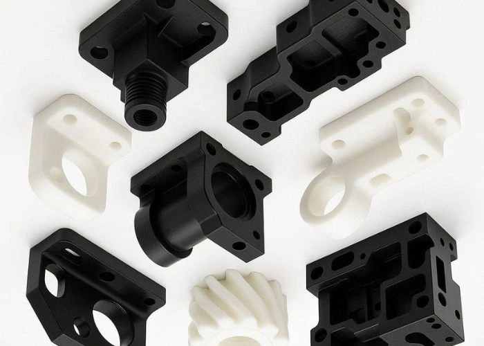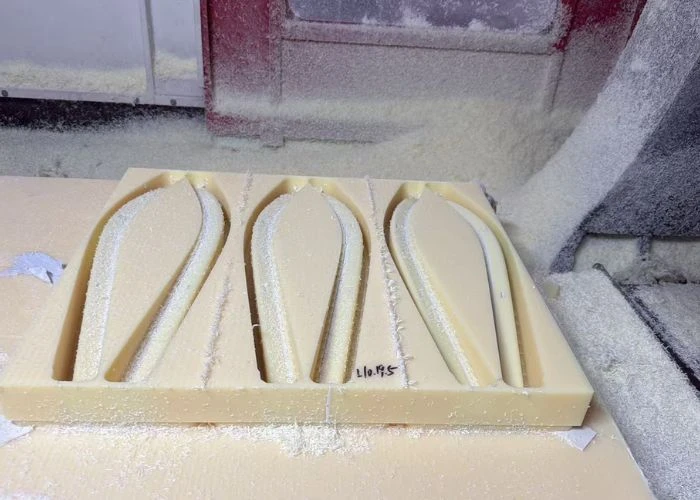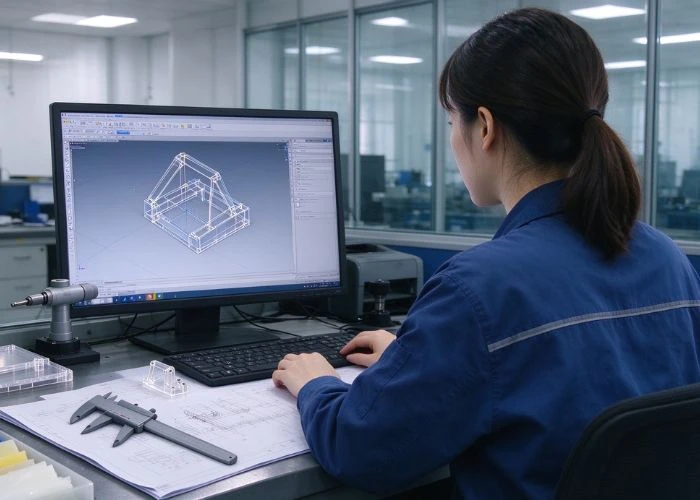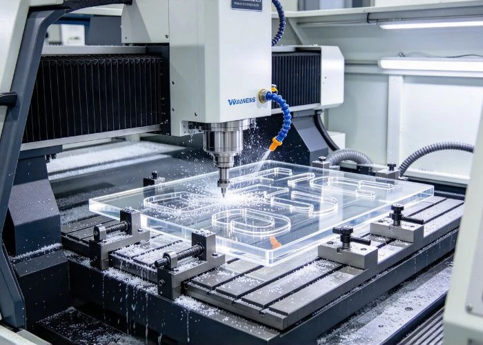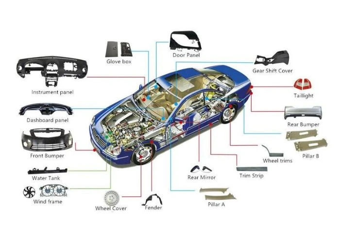

Rapid prototyping helps engineers turn digital designs into physical parts quickly enough to evaluate ideas, identify problems, and improve products before committing to larger manufacturing investments. However, speed alone does not make a prototype useful. Its material, geometry, manufacturing process, and intended evaluation must also support the development decision. From CNC plastic machining and 3D printing to vacuum casting and prototype assembly, different methods provide different kinds of evidence. In this guide, I explain how rapid prototyping works, where each method fits, what affects cost and lead time, and how to choose an effective approach.
What Is Rapid Prototyping?
Rapid prototyping is the process of creating physical representations of a product or component through relatively fast manufacturing methods. I use it to support design evaluation, engineering communication, and product improvement before production decisions become expensive to reverse. Unlike a final production process, rapid prototyping often prioritizes learning, flexibility, and the ability to revise a design efficiently.
A rapid prototype may be a simple shape model, a dimensionally controlled engineering component, a finished appearance sample, or a group of parts assembled into a product representation. The appropriate level of detail depends on what the development team needs to learn.
Rapid prototyping is frequently associated with additive manufacturing, but the two terms are not interchangeable. According to the U.S. National Institute of Standards and Technology (NIST), additive manufacturing creates three-dimensional parts by building material layer by layer. Rapid prototyping is broader because it can use additive, subtractive, casting, and other manufacturing methods to produce physical prototypes.
In practical plastic prototyping, I distinguish between a part that looks correct and one that can provide reliable engineering feedback. A visually accurate model may be sufficient for a design presentation, but evaluating a fastening interface or moving mechanism may require more representative materials and tighter dimensional control.
How Does the Rapid Prototyping Process Work?
A successful rapid prototyping process follows a development loop rather than a simple sequence of ordering and receiving parts. I begin by identifying what must be evaluated, then select the appropriate material, manufacturing method, and inspection requirements. The physical result is reviewed against those objectives, and the findings determine whether the design can advance or requires another revision.
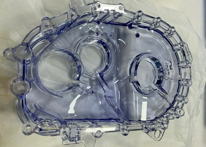
In a typical rapid prototyping project, I start by reviewing the product design, CAD files, and engineering requirements to understand what the prototype needs to demonstrate. Before manufacturing, I check the geometry, material requirements, critical dimensions, and potential manufacturing difficulties. These findings help determine whether CNC machining, 3D printing, or another process is the most appropriate choice.
Once the manufacturing approach is confirmed, the parts are produced, inspected, and prepared for evaluation. Engineers can then assess dimensional accuracy, component fit, appearance, or other project-specific requirements. If the results reveal design problems, the CAD model is revised and another prototype may be manufactured. This process continues as needed until the design provides sufficient evidence for the next development stage.
The process begins with a clear engineering objective. For example, a team developing a plastic housing may need to confirm internal component clearance, fastening positions, and access for assembly. Those requirements influence the prototype more directly than a general instruction to manufacture the part as quickly as possible.
Next, I review the CAD geometry and manufacturing information. Wall thickness, deep cavities, small features, material availability, critical dimensions, and finishing requirements can all affect process selection. Identifying these conditions before manufacturing reduces the chance of discovering avoidable problems after the parts are completed.A practical DFM review for plastic prototyping can help identify machining constraints and unnecessary manufacturing complexity before the first prototype is produced.
Once the prototype is manufactured, its value comes from evaluation. Measurements, trial fitting, visual inspection, and application-specific checks should produce findings that the engineering team can use. A revision is worthwhile when it addresses a defined problem rather than simply creating another version of the same design.
What Are the Main Rapid Prototyping Methods?
Several manufacturing methods can support rapid prototyping, but they differ in how they create geometry, which materials they use, and what the resulting parts can represent. I do not consider one method universally superior. The better choice depends on whether the project prioritizes material behavior, geometric complexity, visual appearance, dimensional control, or the need for several similar components.
CNC Machining for Rapid Prototyping
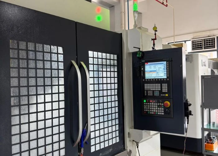
CNC machining removes material from solid stock using computer-controlled cutting tools. In plastic prototype manufacturing, I use this method when a component needs controlled dimensions, actual engineering-plastic stock, or mechanical features that must interact with other parts.
CNC plastic machining is especially useful for components made from ABS, PC, PMMA, POM, PP, PA, and other machinable plastics. It can support mounting features, mating surfaces, threaded inserts, and dimensional relationships that are important during physical evaluation.
However, CNC machining has its own constraints. Tool access, workholding, cutter diameter, internal corners, and material deformation may affect manufacturability. A highly complex enclosed internal structure, for example, may be more practical to produce using an additive process.
3D Printing for Rapid Prototyping
3D printing builds components layer by layer from digital geometry. It is widely used in rapid prototyping because it can produce complex shapes without conventional cutting access or dedicated production molds. This makes it valuable when the design is still changing or when internal features would be difficult to machine.
SLA printing uses photopolymer resin and can produce detailed surfaces and fine features. SLS uses a laser to fuse polymer powder, commonly nylon-based materials, and can manufacture complex components without the same support structures required by many resin-printing processes.
Other technologies, including FDM and MJF, also play important roles in the wider rapid prototyping industry. Their inclusion in a process comparison does not mean every manufacturer offers them. At UForProto, our in-house rapid 3D printing services focus on SLA and SLS.
Material interpretation is important. A resin described as ABS-like may reproduce certain characteristics associated with ABS, but it is not the same material as machined or molded ABS. I therefore avoid treating a printed sample as proof of production-material performance without examining the relevant differences.
Vacuum Casting and Other Rapid Prototyping Methods
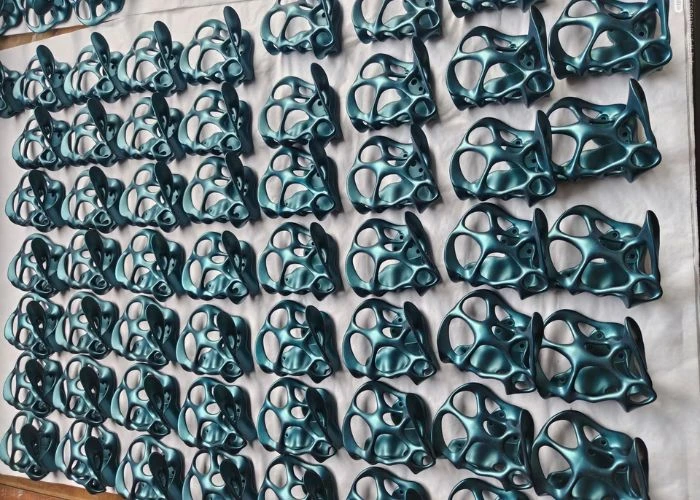
Vacuum casting uses a master pattern and a silicone mold to reproduce polyurethane resin parts. I consider it when a project needs multiple similar prototypes, consistent visual characteristics, or a small batch of components for assembly and presentation.
The resulting cast material may simulate selected characteristics of a target plastic, but it should not automatically be treated as identical to the final thermoplastic. Silicone molds also have practical limits related to geometry, mold life, and part consistency.
Other rapid prototyping routes include sheet-metal fabrication, prototype tooling, and low-volume molded samples. These may be relevant when the product contains metal structures or when an engineering team needs evidence that only a production-like molding process can provide.
Rapid Prototyping Method Comparison
| Method | Main Strength | Best Application | Main Limitation |
| CNC machining | Actual machinable engineering-plastic stock; controlled geometry | Functional parts, mating interfaces, engineering evaluation | Tool access and machining complexity |
| SLA 3D printing | Fine detail and surface quality | Appearance models, detailed geometry | Photopolymer properties may differ from production plastics |
| SLS 3D printing | Complex geometry; powder-supported builds | Complex functional shapes, nylon prototypes | Surface texture, tolerances, and material-grade differences |
| Vacuum casting | Reproducing several similar resin parts | Appearance samples, assembly sets, small prototype batches | Cast resin and silicone mold limitations |
| Prototype tooling | Parts made under more representative molding conditions | Process-dependent molding evaluation | Additional tooling cost and preparation |
The comparison shows why rapid prototyping methods should be evaluated by their intended result rather than by speed alone. A machined plastic component may provide stronger evidence about a particular material interface, while a printed model may be more efficient for assessing a complex geometry that is still evolving.
What Materials Are Used in Rapid Prototyping?
Material selection affects what a rapid prototype can demonstrate and how confidently its results can be interpreted. I consider not only strength or appearance but also stiffness, thermal behavior, chemical exposure, moisture sensitivity, and the way a material responds to the selected manufacturing process. Two prototypes with identical geometry can behave differently if their materials are not equivalent.
Engineering thermoplastics are widely used for machined prototypes. ABS provides a useful balance of processability and mechanical performance, while PC is often selected when toughness or transparency-related requirements matter. PMMA is relevant to optical appearance, POM to low-friction mechanical components, and PP to applications where chemical resistance or flexible behavior is important.
PA materials can provide useful toughness and wear-related characteristics, although moisture absorption may influence dimensions and properties. Even within the same polymer family, grades, fillers, stock form, and processing history can change the resulting behavior.
For 3D printing, material selection is tied closely to the printing technology. SLA commonly uses photopolymer resins, while SLS commonly uses nylon powders. Vacuum casting generally uses polyurethane casting systems formulated to achieve particular appearance or mechanical characteristics.
In my experience, the most important question is not whether a prototype material is generally described as strong, durable, or engineering-grade. It is whether the selected material represents the particular property that the team intends to evaluate.
What Are the Benefits and Limitations of Rapid Prototyping?
Rapid prototyping can improve product development by making design decisions less dependent on assumptions. Physical parts allow engineers to inspect geometry, communicate design intent, and identify problems that may be difficult to recognize in CAD alone. However, the benefits depend on choosing an appropriate prototype, and every manufacturing method has limits that affect how its results should be interpreted.
One major benefit is faster design feedback. Instead of waiting until a production tool is completed, engineers can evaluate physical proportions, interfaces, assembly access, and selected mechanical features earlier in development. This makes it easier to identify changes while the design is still flexible.The rapid prototyping guide published by Formlabs also explains how physical prototypes support concept evaluation, engineering communication, and repeated design improvement during product development.
Rapid prototyping also improves communication between design, engineering, purchasing, and manufacturing teams. A physical sample can make a clearance problem, surface expectation, or assembly concern easier to understand than a drawing alone.
Another advantage is the ability to explore alternatives before committing to expensive production decisions. A team may compare two housing geometries, different mounting positions, or alternative component layouts using physical prototypes rather than relying entirely on simulation and design reviews.
Nevertheless, prototypes do not reproduce every condition of final manufacturing. A CNC-machined part does not automatically predict injection-molding shrinkage, and an SLA model does not necessarily represent the long-term behavior of an engineering thermoplastic. Surface finish, anisotropy, internal stress, and process-specific defects may also differ.
I therefore treat rapid prototyping as a way to reduce selected uncertainties, not as a guarantee that every aspect of a product has been validated. The prototype must be evaluated within the limits of its material and manufacturing process.
What Is Rapid Prototyping Used For?
Rapid prototyping is used wherever physical evidence can improve a product development decision. I see its value across concept evaluation, engineering verification, assembly planning, and customer presentation. Although these applications may involve similar manufacturing technologies, they place different demands on prototype accuracy, material representation, finishing, and the number of parts required.
In consumer electronics, rapid prototyping helps teams evaluate enclosure proportions, button locations, connector openings, and the relationship between internal components and external housings. A printed model may be sufficient for early ergonomic evaluation, while a machined engineering-plastic housing may be more useful when dimensional interfaces become critical.
For medical and beauty device development, physical prototypes can help evaluate housing geometry, component positioning, assembly access, and cosmetic appearance. These evaluations support product development, but they do not replace formal safety, performance, biocompatibility, or regulatory testing when such testing is required.
In robotics and industrial equipment, I often consider interfaces between moving components, protective covers, mounting brackets, and service-access features. The prototype may reveal interference or accessibility problems that are difficult to judge from individual CAD models, especially when several components must operate within limited space.
Rapid prototyping is also useful for stakeholder reviews. A finished appearance prototype can communicate product scale, surface treatment, graphics, and assembly quality more effectively than digital renderings alone. In this situation, visual consistency may matter more than reproducing every mechanical property of the final product.
What Determines Rapid Prototyping Cost and Lead Time?
Rapid prototyping cost and lead time depend on more than the selected manufacturing technology. I evaluate geometry, material, quantity, dimensional requirements, finishing, inspection, and assembly before estimating the work involved. Two parts that appear similar can require substantially different manufacturing effort, and the fastest machining operation does not necessarily produce the shortest overall delivery schedule.
Why Can Similar Prototypes Have Different Costs?
Manufacturing cost is influenced by the actual operations needed to create the part. A simple CNC-machined cover may require limited setups and straightforward toolpaths, while a visually similar cover with deep pockets, thin walls, small internal features, and multiple critical surfaces may require more programming, careful workholding, and additional inspection.
Material choice also changes cost. Some engineering plastics are more expensive or harder to source in the required stock dimensions. Others need careful machining conditions because heat, internal stress, or flexibility can affect the finished geometry.
Quantity affects the economics differently across processes. CNC machining may be practical for one or several parts, while vacuum casting may become useful when several similar resin components are required. However, the master pattern, silicone mold, finishing, and inspection must be included when comparing total project cost.
I also separate essential requirements from optional refinements. If a prototype is intended only for internal fit evaluation, cosmetic painting or decorative graphics may add cost without improving the engineering result. Those operations become valuable when appearance itself is part of the evaluation.
Why Does Manufacturing Time Differ From Total Lead Time?
Manufacturing time refers to the time spent producing the component, while total lead time includes preparation and all work required before delivery. CAD review, material preparation, programming, machining or printing, post-processing, inspection, finishing, and assembly may all contribute to the schedule.
For example, a plastic housing may be machined relatively quickly but still require manual finishing, painting, curing, dimensional inspection, and trial assembly. These operations cannot always be completed simultaneously, and their sequence may determine the earliest practical delivery date.
In a multi-part prototype build, the schedule is often controlled by the slowest critical component or operation. I therefore prefer to evaluate the entire manufacturing route instead of promising a delivery date based only on machine cycle time.
A complete RFQ helps make these estimates more reliable. CAD files, material requirements, quantities, critical dimensions, surface expectations, and the required delivery date allow a manufacturer to identify potential constraints before production begins.
How Should Engineers Choose the Right Rapid Prototyping Method?
Choosing a rapid prototyping method requires matching the manufacturing process to the uncertainty the prototype is intended to resolve. I begin with the evaluation objective, then consider material fidelity, geometry, dimensional requirements, quantity, appearance, and schedule. The goal is not to reproduce every characteristic of the final product immediately, but to obtain reliable evidence for the next decision.
For an early enclosure concept, geometry and appearance may be the main priorities. SLA printing can be effective when the team needs to evaluate shape, proportions, and detailed features quickly. At this stage, using the final engineering thermoplastic may not be necessary if material behavior is not being tested.
The decision changes when a prototype must support mechanical interfaces. Consider a plastic housing with screw bosses, mating surfaces, and a sliding component. If the team needs to evaluate actual material stiffness, local deformation, or dimensional interaction, CNC plastic machining from suitable engineering-plastic stock may provide more relevant evidence than a visually similar resin print.
For a project requiring several finished samples, quantity and appearance consistency become more important. Vacuum casting may be appropriate when the team needs repeated resin components for assembly review or customer presentation, provided the material limitations are acceptable
What Is Rapid Prototyping Used For?
Rapid prototyping is used across product development stages, from early concept evaluation to the preparation of engineering designs for manufacturing. I find it particularly valuable when a physical component can reveal information that drawings, renderings, or simulations cannot fully communicate. The application determines whether the prototype should emphasize appearance, mechanical behavior, dimensional relationships, or the interaction between multiple components.
In consumer electronics, I often see rapid prototyping used to evaluate plastic housings, button positions, connector openings, and internal component arrangements. A housing may appear correct in CAD but reveal unexpected assembly interference when combined with a circuit board, display, battery, or fastening components.
Medical and beauty device development presents another application. Plastic prototypes can help teams examine enclosure geometry, component access, surface appearance, and the physical arrangement of user-facing features. These evaluations support product design decisions, although prototype manufacturing alone does not establish regulatory compliance, clinical performance, or complete device functionality.
For industrial equipment and robotics, I frequently consider mounting interfaces, moving-part clearance, protective covers, and mechanical component relationships. A rapid prototype can reveal whether a component is accessible during assembly or whether its physical geometry interferes with nearby structures.
Appearance evaluation is also important. Color, texture, gloss, graphics, and visible part transitions can influence how a product is perceived. When these characteristics matter, surface finishing and physical assembly may be just as important as the method used to manufacture the underlying plastic components.For products involving several interacting components, complete prototype services can bring part manufacturing, surface finishing, and trial assembly into one coordinated physical build.
For me, the common purpose across these applications is to replace uncertain assumptions with observable physical evidence. The specific evidence changes by industry, but the underlying value of rapid prototyping remains the same.
What Determines Rapid Prototyping Cost and Lead Time?
The cost and lead time of rapid prototyping depend on more than the size or appearance of a component. In my manufacturing experience, material selection, geometric complexity, machining requirements, quantity, finishing, and inspection can all influence the final quotation and delivery schedule. Understanding these factors helps engineers and purchasing teams compare manufacturing proposals more accurately and avoid unrealistic expectations.
Why Can Similar Prototypes Have Different Costs?
Two plastic components may have similar external dimensions but require significantly different manufacturing effort. A simple housing with accessible surfaces may be relatively straightforward to machine, while another housing of the same size may contain deep pockets, thin walls, narrow internal features, or multiple precision interfaces.
In CNC plastic machining, these differences can affect programming, tool selection, workholding, machining time, and the number of setups required. Thin or flexible features may also need additional support or more conservative cutting conditions to reduce deformation.
Material selection creates another cost difference. Common engineering plastics may be readily available in suitable stock sizes, while specialized grades, unusual thicknesses, or larger material blanks can increase purchasing costs and preparation time.
Surface finishing can further influence the quotation. A prototype requiring only deburring and basic cleaning has different manufacturing requirements from one needing extensive sanding, painting, silk-screen printing, or decorative finishing.
Quantity should also be considered. Producing several identical parts may allow programming and setup effort to be distributed across the batch, but the relationship is not always linear. The selected manufacturing process and any additional tooling requirements still determine whether a larger quantity provides a meaningful cost advantage.
When reviewing a quotation, I recommend considering the complete manufacturing scope rather than comparing unit prices alone. Material specifications, critical dimensions, finishing requirements, inspection expectations, and assembly responsibilities should be consistent across competingmanufacturing proposals.
Why Does Manufacturing Time Differ From Total Lead Time?
Manufacturing time refers to the time required to produce a component, while total lead time includes the activities needed before and after manufacturing. In rapid prototyping, engineering review, material preparation, programming, inspection, finishing, and assembly can all affect the final delivery schedule.
For example, a plastic housing may require only a relatively short machining operation, but painting and decorative finishing can add preparation, curing, and inspection time. Similarly, a prototype assembly containing several components may not be ready until the final required part has been completed and checked.
I also consider the relationship between different manufacturing operations. Some activities can proceed in parallel, while others must follow a fixed sequence. When a project requires machining, sanding, painting, silk-screen printing, and assembly, the order of these operations can influence the delivery schedule as much as the machining time itself.
For purchasing teams, I recommend confirming whether a quoted lead time refers to manufacturing completion, final inspection, or shipment readiness. These milestones are not necessarily the same, particularly for prototypes involving multiple parts or surface-finishing operations.
How Should Engineers Choose the Right Rapid Prototyping Method?
Selecting the right rapid prototyping method requires balancing the purpose of the prototype with its material, geometry, quantity, appearance, and delivery requirements. I begin with the engineering decision the prototype must support rather than assuming that the fastest or least expensive manufacturing method is automatically the best choice. Different evaluation objectives can justify different manufacturing approaches, even for similar parts.
When material behavior is critical, I first examine whether the prototype must use the intended engineering plastic. For example, a POM component designed to interact with a moving mechanism may require actual POM stock to evaluate its physical interface and selected mechanical characteristics. In this situation, CNC plastic machining may provide more relevant evidence than a photopolymer model with similar geometry.
However, when the primary concern is geometric complexity or rapid design iteration, 3D printing may be more appropriate. A component containing intricate internal channels or frequently changing structural features may be easier to manufacture additively than through multiple CNC setups.
Quantity changes the decision again. If a development team needs several similar plastic housings for assembly evaluation or customer presentation, vacuum casting may be worth considering after a suitable master pattern has been prepared. Its usefulness depends on the required material properties, geometry, finishing, and number of parts.
I also pay attention to the relationship between dimensional requirements and visual requirements. A transparent cover intended for appearance evaluation may prioritize optical clarity and surface quality, while a mechanical bracket may place greater emphasis on mounting positions, stiffness, and dimensional relationships.
A practical approach is to identify which characteristics must be representative and which can be simplified. Not every prototype needs production-like materials, cosmetic finishing, and tight tolerances simultaneously. Applying unnecessary requirements can increase manufacturing cost and lead time without producing more useful engineering evidence.
For projects involving several components, I may also recommend combining manufacturing methods. CNC machining can be used for critical engineering parts, 3D printing for complex noncritical geometry, and vacuum casting for repeated appearance components. The final choice should support the product’s development objectives rather than force every component into a single process.
How Can Rapid Prototyping Accelerate Development Without Creating Rework?
The value of rapid prototyping depends on how efficiently physical results are converted into engineering decisions. I have found that manufacturing a prototype quickly does not always shorten the overall development cycle if the wrong material, incomplete design information, or unclear evaluation requirements lead to another build. Reducing unnecessary revisions requires coordination between design intent, manufacturing feasibility, and the feedback collected from each prototype.
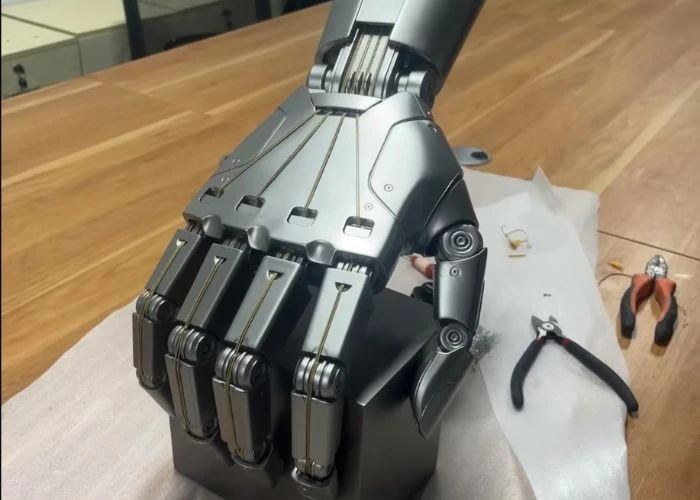
Why Is the Fastest Prototype Not Always the Best Choice?
A fast prototype is useful only when it can answer the intended engineering question. For example, an SLA-printed housing may be produced efficiently for appearance review, but it may not provide the same material response as a housing machined from engineering-plastic stock. If the next decision depends on material stiffness or fastening behavior, the initial prototype may be insufficient.
The opposite situation can also occur. Manufacturing an early concept model through a demanding CNC process may add unnecessary programming and machining effort when the design team only needs to compare overall proportions or component placement.
I therefore consider the total development effort, not just the manufacturing time of one prototype. A slightly longer initial manufacturing process may be worthwhile if it provides more reliable evidence and prevents an avoidable additional revision.
How Should Engineering Feedback Guide the Next Prototype Revision?
Engineering feedback becomes valuable when observations are connected to specific design requirements. Instead of recording only that two parts do not fit correctly, I recommend identifying the affected interface, measured deviation, assembly condition, and possible source of the problem.
For example, an assembly gap may result from an incorrect CAD dimension, machining variation, component deformation, finishing thickness, or the accumulation of several dimensional deviations. Rebuilding the same parts without identifying the cause may reproduce the problem.
I also distinguish between design changes and manufacturing corrections. A design change modifies the intended geometry or function, while a manufacturing correction addresses a deviation from the approved requirements. Keeping these separate helps prevent unnecessary CAD revisions when the underlying issue is actually related to production or inspection.
For each revision, I recommend recording the reason for the change, the expected improvement, and the specific characteristic that must be checked in the next prototype. This creates a clearer development history and makes subsequent engineering reviews more efficient.
How We Manufacture Rapid Plastic Prototypes at UForProto
At UForProto, we manufacture plastic prototypes directly rather than acting as a trading company. Our work focuses on turning engineering designs into physical plastic components through CNC machining, SLA/SLS 3D printing, vacuum casting, surface finishing, and prototype assembly. I approach each project by reviewing its manufacturing requirements and determining which available processes can best support the intended prototype.
Our plastic prototyping work begins with the information supplied by the customer. CAD files, material specifications, quantities, critical dimensions, surface requirements, and assembly expectations help us evaluate manufacturing feasibility and prepare a more accurate quotation.
For components requiring engineering-plastic materials and controlled geometry, we can use CNC plastic machining. When complex geometry or fast physical visualization is more important, SLA or SLS printing may be appropriate. Vacuum casting provides another option when a project requires multiple similar resin prototypes.
Surface finishing and prototype assembly can be coordinated when the project requires a more complete physical product representation. This is particularly relevant for plastic housings, cosmetic components, and assemblies containing several manufactured parts.
Our scope is prototype manufacturing and related assembly work. We do not provide injection molding or complete-device functional testing. Where production-process validation or specialized product testing is required, those activities should be addressed through appropriately qualified providers.
Engineers and purchasing teams can send us CAD drawings and project requirements for manufacturing review and quotation. Providing the intended application and important evaluation requirements also helps us understand what the prototype needs to achieve.
Conclusion
Rapid prototyping is most effective when manufacturing decisions are aligned with the questions engineers need to answer. CNC machining, 3D printing, vacuum casting, and other methods offer different advantages, but no single process is ideal for every product. Material representation, geometric requirements, cost, lead time, and evaluation objectives should guide the selection. I recommend treating each prototype as a source of engineering evidence rather than simply a finished physical model. By defining requirements clearly, reviewing manufacturability, and using feedback to guide revisions, development teams can reduce uncertainty, avoid unnecessary rework, and make more informed decisions before committing to production.
FAQs
1. What Is Rapid Prototyping?
Rapid prototyping is the use of relatively fast manufacturing methods to create physical models or components from digital designs. I use it to support engineering evaluation, design communication, and product improvement before larger production investments are made.
2. What Are the Main Rapid Prototyping Methods?
Common rapid prototyping methods include CNC machining, SLA and SLS 3D printing, FDM, MJF, vacuum casting, and prototype tooling. The appropriate method depends on geometry, material requirements, quantity, and the characteristics that must be evaluated.
3. Is Rapid Prototyping the Same as 3D Printing?
No. 3D printing is one manufacturing method used in rapid prototyping. Rapid prototyping is a broader product development activity that can also use CNC machining, vacuum casting, and other processes. I select the method according to the intended engineering outcome.
4. What Materials Can Be Used for Rapid Prototyping?
Rapid prototyping materials include engineering thermoplastics such as ABS, PC, PMMA, POM, PP, and PA, as well as photopolymer resins, nylon printing powders, and polyurethane casting resins. Material availability depends on the manufacturing process, and prototype materials may not always represent final production materials.
5. How Much Does Rapid Prototyping Cost?
Rapid prototyping cost depends on material, part size, geometric complexity, manufacturing method, quantity, tolerances, finishing, and inspection requirements. I recommend requesting a quotation based on actual CAD files and project specifications rather than relying on a general price estimate.
6. How Long Does Rapid Prototyping Take?
Lead time varies with manufacturing complexity, material availability, quantity, and finishing requirements. Simple parts may be completed within a few days, while assemblies or prototypes requiring multiple processes can take longer. I recommend confirming whether the quoted schedule includes inspection, finishing, and readiness for shipment.